Posted in Architecture

Introduction to IAM Architecture (v2) by IDpro

Abstract

In this section of the BoK, you will explore several conceptual architectures and how they enable IAM solutions across your enterprise. IAM touches all aspects of an organization’s IT environment whether it’s the HR system, email system, phone system or corporate applications, they all need to interface to the IAM environment. Whether it is by supporting the enforcement of user provisioning rules or validating the access of non-corporate users, IAM will always play a role in making IT operations efficient and secure. An architectural approach will heighten the probability that a consistent and comprehensive IAM solution will be achieved.

Keywords: Identity, Access Management, Architecture, Identity Lifecycle

How to Cite:

Cameron, A. & Williamson, G., (2020) “Introduction to IAM Architecture (v2)”, IDPro Body of Knowledge 1(6). doi: https://doi.org/10.55621/idpro.38

PUBLISHED ON 
18 JUN 2020
PEER REVIEWED
LICENSE
CREATIVE COMMONS ATTRIBUTION-NONCOMMERCIAL-NODERIVS 4.0

Introduction to IAM Architecture (v2)

By Andrew Cameron and Graham Williamson

© 2021 Andrew Cameron, Graham Williamson, IDPro

To comment on this article, please visit our GitHub repository and submit an issue.

Note: IDPro® does not endorse a particular architecture framework. IAM practitioners will face many different approaches and must adopt the model that best suits their organizations.

Introduction

Identity and Access Management (IAM) touches all aspects of an organization’s IT environment. Whether it is the human resources (HR) system, email system, phone system, or corporate applications, each system needs to interface to the IAM environment. IAM will always play a role in making IT operations efficient and secure, by supporting the enforcement of user provisioning rules, as an example, or validating the access of non-corporate users. An architectural approach to developing IAM systems will heighten the organization’s probability of achieving a consistent and comprehensive IAM solution.

If the organization maintains an enterprise architecture (EA), any IAM solution they deploy must adhere to the enterprise models and be reflected in the organization’s EA artifacts. This article provides a basic approach for IAM professionals to consider whether or not there is an EA in place.

Terminology

  • Access Management: the use of identity information to provide access control to protected resources such as computer systems, databases, or physical spaces.
  • Architecture: a framework for the design, deployment, and operation of an information technology infrastructure. It provides a structure whereby an organization can standardize its technology and align its IT infrastructure with digital transformation policy, IT development plans, and business goals.
  • Architecture Overview: describes the architecture components required for supporting IAM across the enterprise.
  • Architecture Patterns: identifies the essential patterns that categorize the IT infrastructure architecture in an organization and will guide the deployment choices for IAM solutions.
  • Enterprise Architecture: an architecture covering all components of the information technology (IT) environment
  • Identity Governance and Administration (IGA): includes the collection and use of identity information as well as the governance processes that ensure the right person has the right access to the right systems at the right time.

Acronyms

  • AP – Application Portfolio
  • BPMn – Business Process Mapping notation
  • BSA – Business System Architecture
  • EA – Enterprise Architecture
  • HTTP – HyperText Transfer Protocol
  • IA – Information Architecture
  • IAM – Identity and Access Management
  • IDaaS – Identity-as-a-Service
  • IGA – Identity Governance and Administration
  • JSON – file structure for the communication of data attributes
  • MFA – Multi-factor Authentication
  • PABX – Private Automatic Branch Exchange
  • PAP – Policy Administration Point
  • PDP – Policy Decision Point
  • PEP – Policy Enforcement Point
  • PIP – Policy Information Point
  • RBAC – Role-based Access Control
  • RESTful API – architecture for a programming interface defining how HTTP methods are to be used
  • SAML – Security Assertion Markup Language
  • SCIM – System for Cross-domain Identity Management
  • SSO – Single Sign-On
  • TA – Technical Architecure
  • XML – eXtensible Markup Language – a file structure for the communication of data attributes

IAM Architecture Overview

IAM professionals must have a vision for the IAM environment that satisfies corporate requirements. Each IAM project must build towards the desired target state. An architectural approach will enable the IAM professional to plan, design, and deploy IAM solutions that are both coordinated and integrated; and combine to form a comprehensive IAM environment that meets corporate stakeholders’ current and projected needs.

Identity management within an enterprise touches virtually all systems in use within the organization. Systems, in this context, comprise computer systems that staff and business partners use in the performance of their job responsibilities and physical access systems, such as a requirement to show an identity pass to gain access to a restricted area. Staff includes contractors; they are typically managed through a different system (many HR systems only accommodate employees) but need access to many of the same corporate systems as employees. Including non-human accounts should also be considered; most organizations have service accounts for machine access to systems. As more automation is incorporated into company operations, access control for sensors or bots should be incorporated in the IAM environment. Including non-human entities in the architecture allows the enterprise to manage their access control in a manner consistent with all other accounts; IAM professionals should consider these entities during the system development planning process.

It is the task of an IAM practitioner to ensure that, wherever and whenever identity information is used within an enterprise, the information is collected and used in a properly designed environment that ensures efficiency, protects privacy, and safeguards integrity. Applying an architectural approach, i.e., developing project requirements within a structured framework, will significantly raise the likelihood that an IAM project will be completed consistently and comprehensively with a controlled impact on stakeholders.

There are four levels that the IAM practitioner should consider when developing a solution architecture:

Simple configuration with a Mainframe application accessed from a monitor

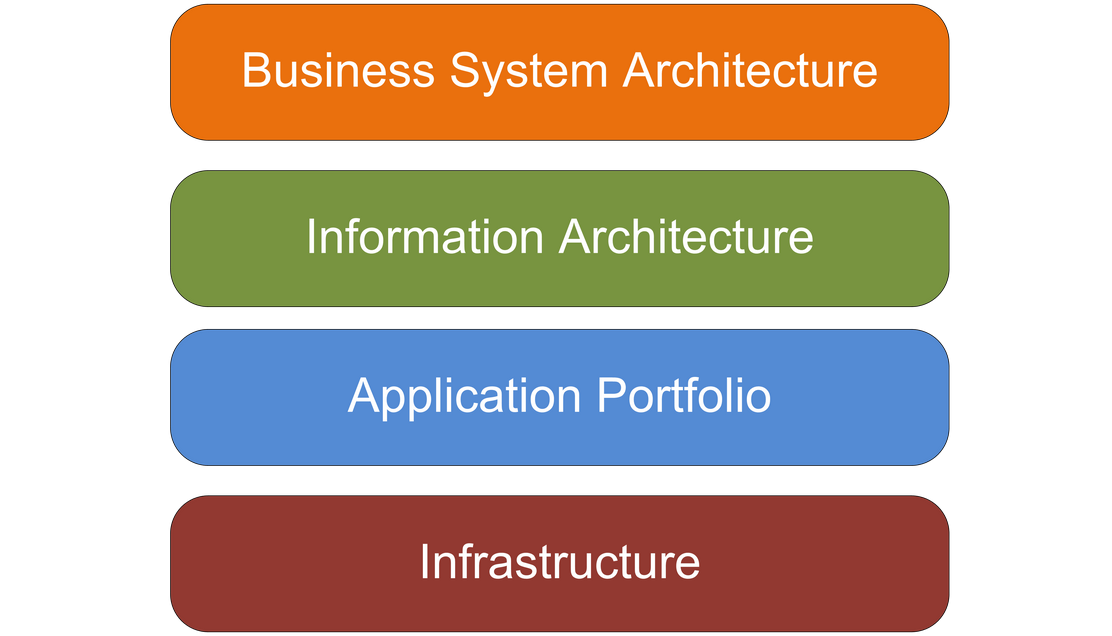
Figure 1: Generic Enterprise Architecture Framework

Business System Architecture (BSA)

Mapping business processes for the collection, usage, and eventual deletion of identity data will greatly assist in understanding the breadth of the IAM task. While BPMn is typically used for business process mapping, the IAM practitioner should adopt whatever tool is typically used in their company.

Considering IT architecture at the business level will facilitate a more holistic approach that considers the identity requirements of all connected systems and ensures consistency in naming conventions. It will also reduce the probability of an IAM project running over budget or over time (a common occurrence when a system owner who has not previously been consulted hears about an IAM project and adds unanticipated requirements).

Information Architecture

It is important to map the identity data elements required by the various applications to the IAM collection, management, and governance systems. This mapping will ensure no application is ‘left behind’ when the IAM systems are re-developed. A useful tool is an ‘entity-relationship diagram’ that maps each attribute collected to each system that requires it. The Information Architecture (IA) should drive consistency between connected systems (e.g., should Firstname, Middle Initial, and Lastname be used, or should Common name, Lastname be used). It should also help define roles (e.g., is this role for a Payroll Clerk or a Financial Officer). The IA should nominate attribute authority (e.g., which system is the authority for phone numbers). Best practice is for the IAM system to be the ‘source of truth’ for identity information in the company (sometimes called the ‘book of record’) because it is typically bad practice for source systems (HR, PABX, etc.) to be queried for data attribute lookups.

The IA becomes the vehicle for ‘identity data orchestration.’ It is the master plan for the collection and use of identity data within an enterprise.

Application Portfolio

An inventory of applications to be included in the IAM project should be conducted.1 How current are they? Are any of the included applications under development? Will the IAM project materially change how each application interacts with the IAM environment? For instance, if an API gateway is being deployed for access to IAM attributes, any application redevelopment should migrate from existing authentication mechanisms to the gateway operation.

A company’s Application Portfolio (AP) becomes an inventory of corporate applications. The record for each application should identify the system owner, type of application (web app, client-server, mainframe, etc.), and its reliance on the IAM environment. Some applications will expect the IAM system to pass authenticated sessions to it. In contrast, others will require user attributes so that it can determine the authorization that a user has to application functionality. The AP should identify the level of integration between each relying application and the IAM system. Web applications will likely pass user requests and responses via HTTP headers. In other scenarios, client-server applications may use an API, while cloud applications may use a SAML request or, if it maintains its own data repository, the SCIM protocol.2

The AP becomes an important record for an organization because it facilitates the planning required as applications are updated.

Technical Architecture

The Technical Architecture (TA) describes, among other things, the technical environment to be supported by the IAM environment. This description will involve understanding the patterns used within the company. Most organizations will have “n-tier” web services and hybrid cloud patterns, but there might still be client-server patterns and potentially mainframe hub-and-spoke patterns. Each additional pattern to be supported will increase the complexity and cost of the project. Often IAM environments with older infrastructure leave out support for legacy technology due to cost considerations, but this fragments the IAM task. Properly constituted, a cost/benefit analysis for deploying legacy connectors will typically be successful.

The TA impacts the IAM environment because different solutions are required for different patterns. For example, a web services pattern will mandate a single sign-on (SSO) environment capable of supporting RESTful APIs and SAML assertions and passing identity attributes in JSON arrays or XML files. An on-premise Windows environment, as another example, will typically use the Kerberos authentication protocol from an AD infrastructure or an LDAP directory. A cloud environment will often require a SAML operation or an Identity-as-a-Service (IDaaS) offering, whereas an older directory should be supported via a connector from the IAM infrastructure.

Additionally, corporate security policy may create requirements that require certain technical decisions. For instance, a requirement to maintain full control and authority over the data and infrastructure may require hosting the entire identity management stack on premises.

Architectural Approach

It is an unfortunate fact that many IAM (identity and access management) projects exceed their scheduled time and budget. The usual reason for this is a misunderstanding of the extent of the project and the systems impacted. The project team tends to focus just on the task at hand, e.g., installing the IAM software package, without realizing that IAM systems within an enterprise touch virtually all other systems in use within the organization. These other systems might include a birthright system such as email, an administrative system such as the Financial Management system, or an operational system such as an Enterprise Resource Management system.

In some circumstances, the change caused by an IAM project will be minimal, with a limited impact on resources. In other cases, the change will be significant, impacting both infrastructure and personnel across the organization. An architectural approach will ensure that a solution architecture is developed for each IAM project to understand the extent of the work required and effectively plan for the change it will generate.

An IAM practitioner’s task is to ensure that, wherever and whenever identity information is used within an enterprise, the information is collected and used in a properly designed environment that ensures efficiency, protects privacy, and safeguards integrity.

For organizations with an EA, understanding how information is collected and used should be quite easy, as it is fundamentally a part of how the systems are deployed. For other organizations, the environment will be a “greenfield,” allowing the IAM practitioner to develop their own architectural approach.

Architecture Patterns

At the Technical Architecture level, a “pattern” approach is useful to understand the supported technology within an organization. For instance: what is the predominant server infrastructure – is it Linux or Windows or both? What server operating system versions are supported? Are VMs used? What is the support for cloud infrastructure – public, private, hybrid? Is AWS, Azure, or Google Cloud supported? Can the scale required for customer IAM be accommodated? For IoT devices – how does the IoT platform integrate with the corporate environment?

The TA will define the computer system “patterns” to be supported by the IAM environment within an organization. For young companies, this will be web-based patterns, either “2-tier” or “n-tier.” Increasingly managed cloud environments are being engaged, potentially with a micro-services approach. But for mature organizations, there will typically be legacy applications with a client-server pattern, or even a mainframe ‘hub and spoke’ pattern, with PCs running terminal emulator software.

The IAM environment must support the selected patterns and ensure a managed approach that adheres to the organization’s governance and cybersecurity policy.

Host

There are few mainframe systems left in service, with notable exceptions in the banking industry and some government installations. The IAM environment will often be required to synchronize to an older data store to support a mainframe system.

Simple configuration with a Mainframe application accessed from a monitor

Figure 2: Mainframe application accessed from a monitor

Client-Server

Client-server environments can present a complex support requirement since many such systems maintain their own identity database to provide fine-grained access control to system functionality. Redevelopment of a client-server application to externalize access control decisions to an authentic authorization server can be a way to harmonize access policies across an organization.

Simple client-server network diagram

Figure 3: Client application access a backend server

N-tier

The most common on-premise application environment these days is an “n-tier” web services infrastructure. While there are many variants, a user accessing the front-end web server will be redirected to an authentication service, usually supporting SSO, with an authentication token passed back to the application in an HTTP header. If the application requires user authentication, the IAM system should set user entitlements as part of the initial provisioning activity when a user joins the organization.

Diagram of client machine connecting through the network to the presentation and application servers as well as the database system.

Figure 4: Common web-services model

Hub & Spoke

Hub and spoke systems are typically only in large transaction processing systems. Often the only IAM touchpoint is access control for DevOps staff via a privileged access management system.

Two client systems connecting through the network to the "ETL" host, which in turn connects to an Internal and an external database

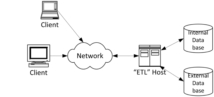
Figure 5: Common data service configuration

Remote Access

Increasingly remote access to corporate systems must be supported. The authentication server must accommodate the required access control mechanisms, from basic LDAP lookups for password accounts to sophisticated MFA environments capable of elevating authentication levels to suit application security requirements. The provisioning task in such environments requires maintaining one or more identity provider services within the enterprise.

Typical enterprise model providing external, remote devices access to corporate applications via a web application firewall or VPN

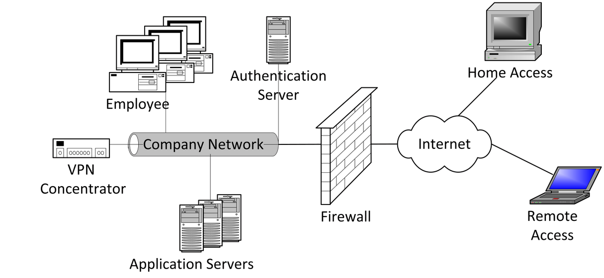
Figure 6: Typical enterprise network access model

Hybrid Cloud Identity

A key indicator of effectiveness in an IAM Architecture is how complexity is managed across the IAM components in the environment. Today, most organizations are leveraging cloud infrastructure platforms in some capacity, either private clouds provided by their technology partners or public clouds such as AWS, Azure, or Google. This raises the issue of how to establish identity as a common control plane between the on-premises environment and the cloud infrastructure. IAM is a critical component of a hybrid IT architecture. Hybrid IAM allows organizations to establish a common credential that can be enabled for access to resources in either on-premises or cloud environments.

The hybrid cloud example assumes an existing ‘source of truth’ to which all enterprise users authenticate; this is typically Active Directory. With the Hybrid IAM pattern, authenticated on-premise users will have access to on-premise, public cloud, or other external services that support common identity standards such as OpenID Connect or OAuth.Hybrid Cloud diagram

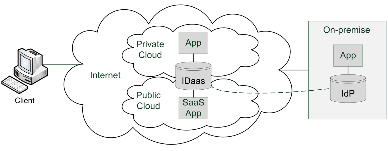
Figure 7: Hybrid Cloud Identity Architecture model

Table 1: Hybrid IAM Architecture components

ComponentDescription
On-Premise (Corporate) DirectoryDirectory service that enables authentication to access enterprise resources (e.g., Active Directory). Typically contains directory objects (accounts) that represent a human (user account) or non-human identity (service account).
On-Premise Federation ServiceIdentity service that implements common access management capabilities (authentication and authorization) for enterprise applications. Typically supports identity standards like SAML or OpenID Connect to enable access to internal or external resources.
Identity Sync ServiceInfrastructure service that monitors directory objects in the enterprise directory for changes and synchronizes changes to a mapped cloud directory object. Sync direction can be one-way or two-way but is typically implemented in an Enterprise to Cloud direction to minimize risk and complexity. Standards such as SCIM can be used for this data transfer.
Cloud IAM ServicePlatform service in a public cloud that implements core IAM capabilities (Authentication, Federation, Access Management) and can be leveraged to access on-premise resources as well.

Important considerations for Hybrid IAM:

  • User Provisioning: User objects can be configured to synchronize when added to either the cloud or the on-premises environment. The best practice is to restrict user provisioning to one environment and sync account and profile data to the other environment (typically from enterprise to the cloud).
  • Profile Data: Manually maintaining identities in more than one environment can add unnecessary complexity and risk to your security posture. Cloud identity objects may not need the entire set of user profile data available for an on-premises user; the IAM practitioner should take care (e.g., understand the business requirements for authentication) when deciding how much user profile data should be stored on a cloud user object. A principle of “least privilege” should be applied to avoid data spillage.
  • Single Sign-On: Cloud IAM environments can enable SSO to on-premises applications or services. For SSO to be successful, the user object must have been provisioned and enabled for sign-in. It is critical to understand the authentication scenarios available from the cloud IAM platform (e.g., pass-through authentication or federation) and ensure that there is a fit with the enterprise requirements.

As enterprises place increasing importance on “time to value”, a hybrid IAM architecture will be critical to support infrastructure expansion beyond the enterprise perimeter and leverage cloud-enabled benefits (e.g., agility, scalability, reliability). The IAM professional will find use-cases where IDaaS solutions offer rapid deployment and appealing software update methods, when compared as an alternative to on-premises solutions. However, hybrid scenarios may require both types of deployments, cloud and on-premise, to working together. In some cases, the cloud identity service will be the ‘source of truth’ for identity data within the organization. Such an IDaaS approach can reduce the overhead of managing on-premise infrastructure for an enterprise, an activity that can be costly and inflexible.

Applying an Architectural Approach

An architectural approach can be taken to an IAM project regardless of whether it is in the collection and management of identity information or access management, using identity information for access control to protected resources.

Identity Governance and Administration

Identity Governance and Administration (IGA) covers the identity management side of IAM, e.g., the ‘admin-time’ events that establish user entitlements, as opposed to ‘real-time’ events that occur when users request access to protected resources. IGA combines administration and governance over the collection, use, and disposal of identity information. It requires a governance facility that enables managers to certify the entitlements that their staff have been granted. In addition, IGA typically includes monitoring and reporting functions for identity services that, in turn, support corporate requirements.

IGA systems support:

  • Administering accounts and credentials
  • Identity and account provisioning
  • Managing entitlements
  • Segregation of duties
  • Role management
  • Analytics and reporting

IGA systems provide additional functionality beyond standard IAM systems. In particular, they help organizations meet compliance requirements and enable them to audit access for compliance reporting. They also automate workflows for tasks such as access approvals and provisioning/deprovisioning.

Identity Lifecycle

The business rules that tie these elements together are generally referred to as the identity lifecycle.3 In the identity lifecycle, an identity is created that defines who or what (human or non-human) needs access to a protected resource. Every stage of the identity lifecycle sees the activities of the identity managed to ensure business rules are enforced according to the identity and security rules of the enterprise.

A graphic of the Identity Lifecycle, starting with Identity Onboarding, then Identity Management, Account Management, Entitlement Management, and Access Management.

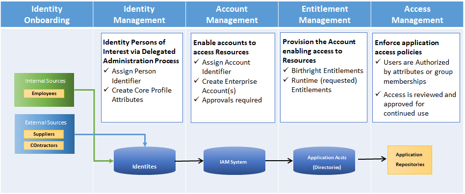
Figure 8: Identity Lifecycle Categories

IGA System Components

Identity governance and administration tools help facilitate identity lifecycle management.

IGA systems generally include the following components for identity administration:

  • Password management: using tools like password vaults or, more often, SSO, IGAs ensure users don’t have to remember many different passwords to access applications.
  • Integration connectors: used to integrate with directories and other systems that contain information about users and the applications and systems they have access to, as well as their authorization in those systems.
  • Access request approval workflows: support the automation of a user’s request for access to applications and systems and ensures all access is properly authorized.
  • Automated de-provisioning: supports the removal of a user’s entitlement to access an application when the user is no longer authorized to access a system.
  • Attestation reporting: used to periodically verify user entitlements in various applications (such as add, edit, view, or delete data) and is usually sent to a user’s manager.
  • Recertification of user entitlements: often a response to an attestation report, recertification of user entitlements involves recording a manager’s approval of their staff’s system access. If access is no longer required, this shifts to automatic de-provisioning.
  • Segregation of duties: rules that prevent risky sets of access from being granted to a person. For example, if a person has the ability to both view a corporate bank account and transfer funds to outside accounts, this might enable a user to transfer money to a personal account.
  • Access reviews: reviews include tools that streamline the review and verification (or revocation) of a user’s access to different apps and resources. Some IGA tools also provide discovery features that help identify entitlements that have been granted.
  • Role-based management: also known as Role-based Access Control (RBAC), this includes defining and managing access through user roles.
  • Analytics and reporting: include tools that log activities, generate reports (including for compliance), and provide analytics to identify issues and optimizations.

IGA Solution Architecture

An example of how an IGA solution could support an authentication service is shown in Figure 9 (access management shown for context):

A diagram of IAM architecture components, including the end user who goes through an Access Gateway to the Authentication Services. There is also the administrative user who handles end-user on and off-boarding and administration through the IA service, Account Management Services Entitlement Management Service, and the Enterprise Applications

Figure 9: IAM Architecture Components

This architecture supports the following IAM Processes:

Table 2: IAM Processes

ProcessDescription
Identity ProvisioningCreates identity records based on initiation from trusted identity sources (e.g., the HR System)
Account ProvisioningCreates accounts in Enterprise Directories based on birthright provisioning rules. Also supports the creation of application accounts based on request / approval workflows.
Entitlement ManagementSupports the workflow and administration requirements of enabling user-to-group/role mappings that enable access management rule creation.

Access Management

Access Management is the ‘real-time’ component of IAM. It encompasses the processes that are critical in protecting corporate resources and securing the digital business. Whether it is giving access to customers to enable e-commerce or securing resources for partners to conduct business securely, the Access Management architecture will control the planning, design, and development of the enabling technology.

Access Management Overview

An access management architecture will have components that enable only those accounts that are authorized to perform an action on a protected enterprise resource.

The key functions supported in an Access Management Architecture are:

  • User Authentication (staff, contractors, business partners)
  • Access Policy Management
  • Access Policy Decision making and enforcement
  • Authorization Control (Coarse / Fine-Grained)
  • Adaptive Access controls
  • Single Sign-On (SSO)
  • Authenticated Session Management
  • Security Token Services
  • Access Event Logging
  • User Behavior Analytics
  • Access Management Solution Architecture

The two most common Access Management services supported in most scenarios are:

  • Authentication – logging into a computer system – typically role-based
  • Authorization – accessing computer system functionality – typically attribute-based
  • Policy-based authorization is increasingly being deployed. It provides access control to corporate resources in accordance with centrally managed corporate policy rather than entitlements established on a system-by-system basis.

An example of a fine-grained authorization environment is shown in Figure 10. The components of the solution combine to control access to corporate resources based on the policies in the Decision Point.

A diagram of the relationship between various Access Management Comonents, including the Policy Enforcement point (PEP), the POlicy Decision Point (PDP), the Policy Access Point (PAP), and the Policy Information Point (PIP).

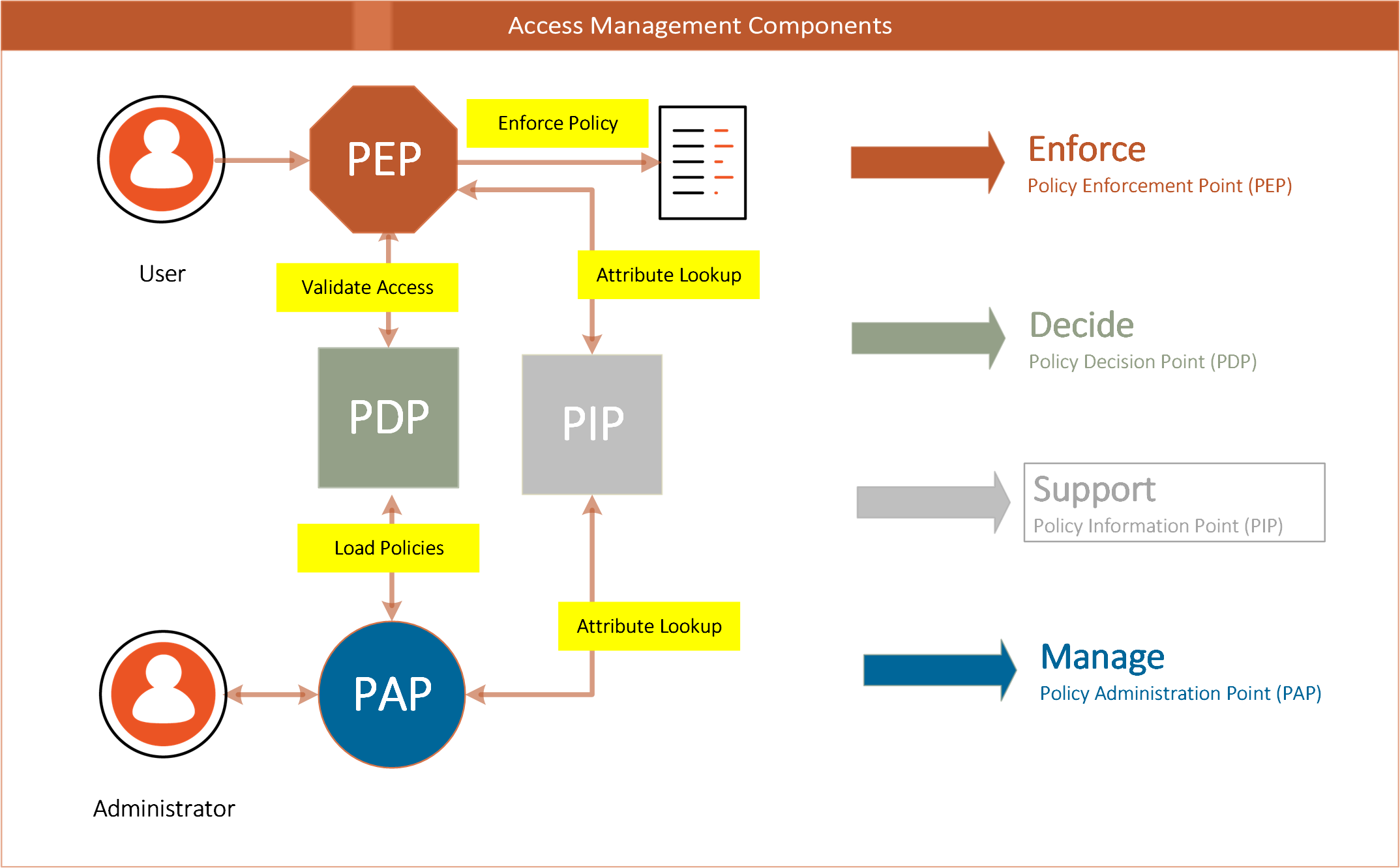
Figure 10: Typical Components of an Authorization Service

The architecture of an authorization service will typically contain the key elements that are involved in the flow from an actor (person or system) on a device (mobile or desktop) that accesses an application or service (typically over the internet) that resides within an enterprise boundary (behind network firewalls).

Table 3: Policy Control Points

Policy Control PointDefinition
Policy Administration Point (PAP)responsible for creating policy statements that tie the user to a role or group and defines the type of access to a resource
Policy Enforcement Point (PEP)responsible for protecting the resource; intercepts traffic to the resource, and validates access with the PDP
Policy Decision Point (PDP)determines access to a resource, uses policy to determine if a subject (user) has access to a resource, usually via an attribute value or role or group membership.
Policy Information Point (PIP)typically a user or attribute store that provide information about managed users (e.g., Active Directory or LDAP directory)

Access Management Patterns

A well-crafted IAM architecture is able to both improve user experience and increase security by combining the flow between architecture components in a connected, orchestrated framework. Historically, organizations have seen security and ease of use as tradeoffs, but with the new identity technologies available today, it is possible to have both.

When combining these key components in a deployment blueprint (solution configuration), an architecture pattern evolves to support most, if not all, access management needs across the organization.

A diagram of possible access management patterns, taking a user from a client such as a browser or mobile app through a DMZ and into a corporate network.

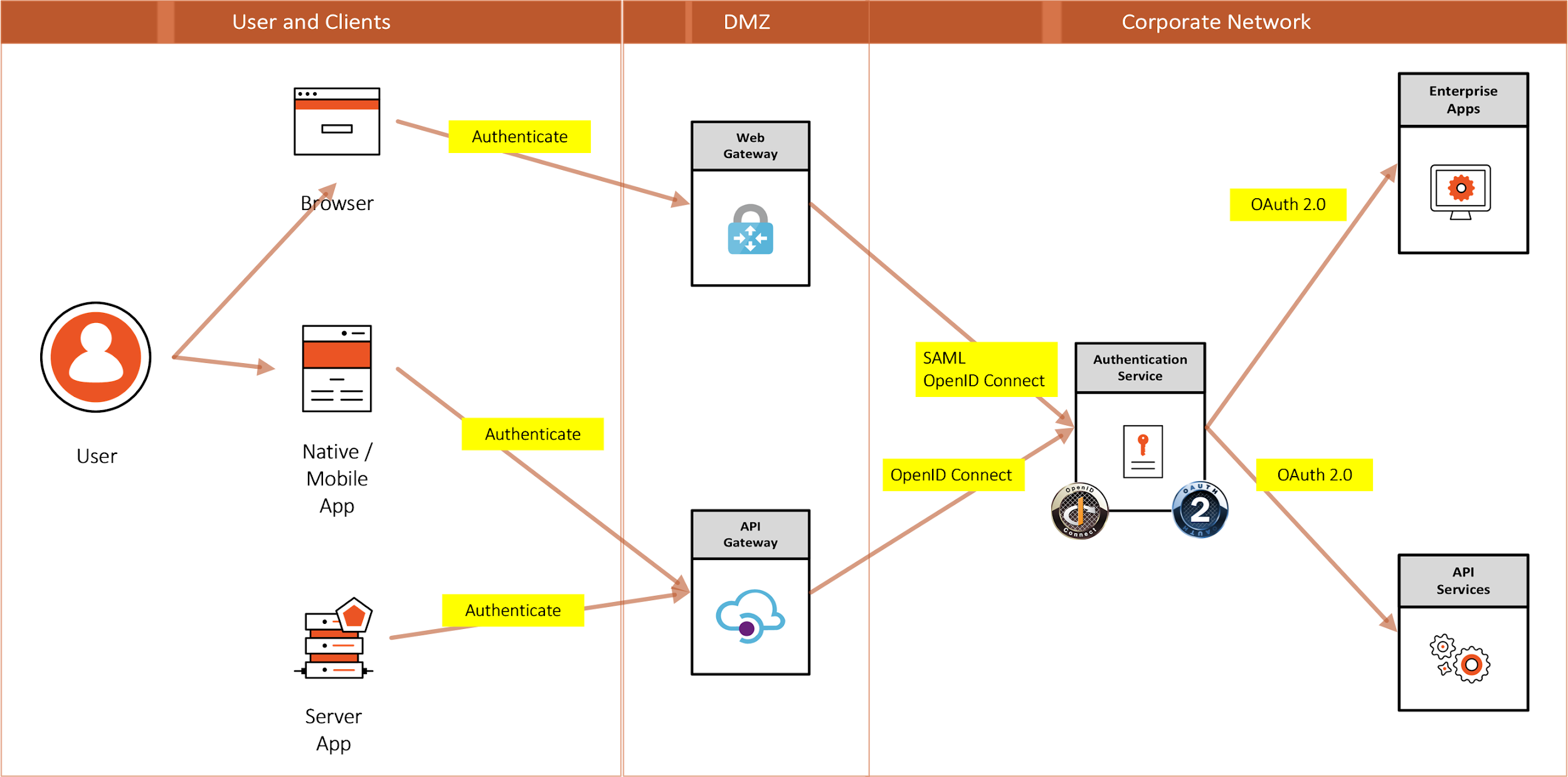
Figure 11: Access Management Patterns

Table 4: Access Management Pattern descriptions

PatternDescription
Browser to Web ApplicationA user needs to sign in to a web application that is secured by an Authentication Service
Native App (also Single Page App) to Web APIA native application needs to authenticate a user to access resources from a web API that is secured by an Authentication Service
Server App to Web APIA server application with no web user interface needs to get resources from a web API secured by an Authentication Service

Identity Standards

No IAM solution architecture is complete without addressing the applicable standards. Because IAM touches virtually all corporate systems, interfaces need to adhere to standards in order to minimize the amount of customization that would otherwise be required. An IAM Architecture should support a “pluggable” approach that facilitates interconnection and ties together key security enablers that are built on industry standards. There are several industry organizations (standards bodies) like IETF, OASIS, Kantara Initiative, and the OpenID Foundation.

The key standards that support modern identity and access management today are OIDC, OAuth2, and SAML.4

Logos for OIDC, OAuth, SAML

Figure 12: Logos for OIDC, OAuth2 , SAML

Conclusion

IAM practitioners should adopt the enterprise architecture approach used within the organization in which they are working. In the absence of a corporate approach to architecture, IAM practitioners should develop an architectural approach that ensures their IAM projects consider all the business systems that might be affected, the types of applications to be supported, and the infrastructure on which IAM solutions are to be deployed.

An IAM project that takes such an approach will have a significantly better chance of being completed within schedule and budget constraints. It will also be much more likely to satisfy users.

Authors 

Andrew Cameron

Photo of authorAndrew Cameron is the Enterprise Architect for Identity and Access Management at General Motors. His responsibilities include Defining the Strategy and Implementation Roadmaps of their IAM technology platform and ensuring the architectural quality of the many initiatives driving the GM digital business.

Graham Williamson

Photo of authorGraham Williamson is an IAM consultant working with commercial and government organizations for over 20 years with expertise in identity management and access control, enterprise architecture and service-oriented architecture, electronic commerce, and public key infrastructure, as well as ICT strategy development and project management. Graham has undertaken major projects for commercial organizations such as Cathay Pacific in Hong Kong and Sensis in Melbourne, academic institutions in Australia such as Monash University and Griffith University, and government agencies such as Queensland Government CIO’s office and the Northern Territory Government in Australia and the Ministry of Home Affairs in Singapore.

Change Log

DateChange
2020-06-17V1 published
2021-09-30Additional information added regarding hybrid cloud infrastructures; removed specific mention of RACF; minor editorial updates

  1. Readers may find the IDPro BoK article “Introduction to Project Management for IAM Projects” of interest. See Williamson, Graham, and Corey Scholefield, “Introduction to Project Management for IAM Projects,” IDPro Body of Knowledge, vol 1, issue 1, March 2020, https://bok.idpro.org/article/id/25/.↩︎
  2. “SCIM: System for Cross-domain Identity Management” http://www.simplecloud.info/↩︎
  3. Cameron, Andrew and Olaf Grew, “An Overview of the Digital Identity Lifecycle,” IDPro Body of Knowledge, 30 October 2021, https://bok.idpro.org/article/id/31/.↩︎
  4. OpenID Connect, website, OpenID Foundation, https://openid.net/connect/; OAuth2, website, https://oauth.net/2/ ; “Security Assertion Markup Language (SAML) V2.0 Technical Overview,” OASIS, http://docs.oasis-open.org/security/saml/Post2.0/sstc-saml-tech-overview-2.0.html↩︎
Posted in Business Processes

Best practices for identity governance and administration

IGA is the branch of identity and access management that deals with making appropriate access decisions. It allows your company to embrace the benefits of hyper-connectivity while ensuring that only the right people have access to the right things at the right times.

When it’s done right, IGA makes security easier and gives you valuable insights about employee activity and needs. When it’s not done right, it puts your company at risk and is perceived as an annoying waste of time. Unfortunately, the not-done-right version is the norm today.

So, what does a strong, successful IGA program look like? Here are five steps for best practices, along with examples to illustrate what works and what doesn’t.

1. Make identity your foundation

In a well-managed Identity Governance and Administration program, access decisions are based on identity, which is the foundation for all security. 

You probably think of identity as the defining attribute of people—your employees, business partners, and customers. But identity isn’t limited to human beings. We have a customer in Australia who raises sheep, some for medical purposes and others for meat or wool. The company needs to track which animals go where, so each sheep has a corporate identity.

Maybe you don’t have sheep to track. But do you have servers, applications, and devices? IoT-connected appliances or vehicles? These things also have identities. An identity should be assigned to anyone or anything that uses or transmits your company’s information.

So the first step in establishing a successful IGA program is to identify all your identities and determine what information they can access. Then you can refine your access decisions based on the amount of risk the information contains.

2. Create a strategic plan

Once you’ve inventoried your identities and mapped their access points—a process infinitely more efficient if it’s automated—you need to make decisions about which permissions to keep and which to change.

Each organization needs to determine its priorities. You should consult with all stakeholders and create a strategic plan for identity management, making sure you include all of your systems, cloud-based and on-premises. Create a common decision-making framework based on risk. 

Many companies like to start with privileged accounts, including root accounts, which belong to administrators and can get into your critical systems and make changes. Because these accounts can do so much, they are a high-value target for attackers.

Privileged accounts should be limited in both number and scope. Many organizations learn the hard way that they are not. At a healthcare company we work with, a root account holder working on the claims database made an error that shut down the company’s operations for an entire day.

It was just a mistake, but it led the company to look into access privileges. It found 100 other account holders who could get into this same sensitive database—far more than necessary.

Any account with unneeded access privileges is a security liability. The more sensitive the information they can get to and the more they can do with it, the higher the risk.

Who determines whether someone should have access to an application or database?

A common myth is that it’s up to the IT department. But IT has no way of knowing whether John in sales needs to see quarterly revenue figures for his department, or which people in DevOps need to understand a patent you’re working on. These decisions should be made by business managers and application owners, with risk-appraisal assistance from IT.

3. Build an agile system

Companies are not static. They spin off assets and acquire other companies. They reorganize departments, shifting people into new roles without informing IT. Partners, contractors, and customers come and go. Service accounts are set up to do their thing and are then disabled—or all too frequently, forgotten. People quit, people are hired, people are fired.

Change is constant, but security often lags behind. Why? Because companies tend to limit their access updates to a time frame set by compliance regulations. Making your quarterly or semiannual deadline may keep you legal, but it also gives hackers months of freedom to exploit loopholes, any one of which could lead to a devastating data breach.

Why risk it? Today’s technology allows you to set up an adaptive governance system that detects and responds to role changes as they happen. It puts the information in front of the right decision makers and makes it easy for them to respond.

In a world of software-as-a-service and instant updates, this is the kind of model people expect. When it comes to security, you don’t ever want to be behind the curve. If you build an IGA program that can scale to include all of your identities and is flexible enough to accommodate the reality of constant change, it will serve you well for years to come.

4. Help stakeholders make decisions

The truth is, line-of-business managers and application owners find reviews a pain, and who can blame them? They’re working overtime to do the best job they can with limited resources. Then this extra task pops up, asking them to review the access of the same people they reviewed three months ago.

“What is the point?” they grumble under their breath. But they dutifully turn their attention to the form at hand.

The business manager knows her staff. She quickly scans the list and sees that the names are right. Some people are using apps she doesn’t recognize, but they probably have a good reason for it. She’ll ask them—someday when she has time.

Here’s someone who just switched to a different department, but maybe he needs to use our database to finish up a project—better not leave him high and dry. Most people have access to many files and apps. Are they using them all? Who knows? They’re getting their work done, so he’ll give them the benefit of the doubt. She clicks Select All, Approve, and is done for another quarter.

The application owner doesn’t personally know all the people using the apps he’s responsible for. How could he? There are hundreds. He makes a halfhearted effort to check a few profiles. Nobody seems obviously wrong.

How is he supposed to make these decisions? Why did they give him this task, especially now, when he has to prepare for a presentation this afternoon? He clicks Select All, Approve, done.

Certification reviews can get better—really

This is the reality of certification reviews. How much do you think they are improving your company’s security posture?

It doesn’t have to be this way. Managers are lax not because they are lazy, but because they lack pertinent information to make informed decisions. You can use your IGA system to help them.

Instead of sending a form with a list of names, look at the analytics your system provides—hopefully on an easy-to-read dashboard. You may learn that of a manager’s 50 employees, 47 are using all the apps and files assigned to them on a regular basis.

But two also have access to high-level financial information. Do they really need it? Another worker doesn’t seem to be using the information assigned to him at all. Has he moved to a different role?

Rather than sending the manager a list of 50 people to review, you send a list of three. And you explain why you need her to review these three. Now she feels like a valued member of a team, instead of a robot commanded to perform an unsuitable task. She is more likely to cooperate and less likely to complain.

Back at your dashboard, you notice an application that requires two levels of approval, but the person managing the first level always gives approval within two minutes. So why not save him some time and cut out that level?

And that business manager who says she doesn’t know which apps her people are using? Show her. Maybe they’ve abandoned an old, inefficient piece of software and downloaded something new. Maybe there’s a more secure enterprise solution the manager can find to increase productivity.

Analytics are your friend

These are the kinds of insights your IGA program can provide when you put it to good use. Study your analytics to find anomalies and outliers that require human intervention, and streamline and automate the rest. Actively seek information that will be useful to managers, and communicate it in plain English instead of technical jargon.

If you do these things often enough, managers will stop saying access review is a curse. They may even come to see it as a blessing.

So will other stakeholders, including your IT security team, compliance managers, and auditors. Because the governance system is adaptive, making changes along the way as people are hired, take on new roles, or leave, these stakeholders have an up-do-date, accurate picture of roles and access at review time—or at any time.

Instead of spending countless hours collecting and analyzing data, they have all the information they need on a dashboard that gives them a bird’s-eye view—or as much granularity as they want.

That means they can make more confident decisions using fewer resources. One client reduced the number of IT staffers reviewing entitlements from 14 to seven.

Intelligible dashboards also allow the security team to literally “show” executives the organization’s progress in improving safety while simultaneously reducing the burden on employees.

5. Don’t forget unstructured data

Managing access to applications is important. But what about the information the applications contain? What about all your emails, PowerPoint presentations, Word docs, videos, podcasts, voice recordings, pictures, and sensor data? Shouldn’t you be cataloging this information, assessing its risk, and determining who should have access to it?

You should, though few organizations are doing it at this point. But they can’t ignore it forever. Unstructured data—information that doesn’t fit neatly onto a spreadsheet—is accumulating like an avalanche as people increasingly use technology to communicate information. If you can’t track this information, how do you know it’s being transmitted and stored securely?

Credit card and Social Security numbers may be lurking in your apps and back-office files without your knowledge. If someone has sent any of this information in an unencrypted email, you already have a de facto data breach on your hands.

It happens, perhaps more often than you think. But if you know what your information contains, you can prevent these kinds of problems.

An IGA system can analyze your unstructured data and alert you if it finds files that look like they contain credit card numbers, dates of birth, Social Security numbers, or other confidential information. When that happens, let the appropriate managers know so that they can delete the information or move it to a more secure location. Then create rules to automate the process.

If managers weren’t grateful for your help before, they will be now. Nobody wants to be responsible for a data breach.

Collaboration is key

In today’s hyper-connected world, having a strong, well-managed IGA program is essential. To be effective, it must be comprehensive, covering all identities and applications on-premises and in the cloud, and unstructured as well as structured data.

Above all, it must be flexible, expanding, and contracting in concert with the enterprise at all times. You need to manage it to provide your managers with useful insights instead of burdening them with unsuitable tasks.

If you follow these IGA best practices, you will lower your company’s exposure to risk and be able to show them the analytics to prove it. You will be able to explain not only what needs to change, but why it needs to change. Security will shift from being a top-down, unwelcome process to an enterprise-wide collaboration. In an ever-changing, fast-moving world, a state-of-the-art IGA program is your best hope for achieving stability.

Posted in Business Processes

How to manage non-employee identities outside of HR?

As a key pillar of an Identity Access Management (IAM) strategy, Identity Governance and Administration (IGA) is the cornerstone of managing and governing identities. As part of IGA, organisations must manage and maintain different types of identities in order to provide the right access to the right people at the right time. In saying that, the first place to start is where the identity originates – the authoritative source. 

No alt text provided for this image

An authoritative data source is a repository that contains attributes of an individual and is the most valid source for this information. In cases where there is a discrepancy between data, the authoritative source is considered to be the most accurate.

IGA solutions rely on authoritative data to be clean, consistent, and complete in order to function as intended. 

While the concept of identifying the authoritative source seems simple enough, many organisations face challenges due to the wide variety of identities and, therefore, multiple governing data sources.

Most organisations have identities that fall into the following four categories:

  • Employee/internal workforce identities
  • Non-employee workforce identities
  • Non-human identities
  • Consumer/external identities

One of the most challenging type of identities to manage is non-employees, think contractors, temporary workers, vendors, etc. Now more than ever, we are seeing clients struggle with non-employees when it comes to tracking what they have access to and managing their on-boarding and off-boarding processes. 

For non-employees, most organisations have separate identity creation processes, as these identities come from multiple external sources and the organisations prefer to avoid owning them in their Human Resource Management System (HRMS). Instead, the Identity and Access Management (IAM) team is usually tasked with creating a centralised process so there is only one authoritative source for the non-employees. 

It is very common amongst organisations to have various non-employee identities, owners, and data sources. This can often lead to some challenges when managing different identities across multiple data feeds. 

We will look to address some of the most common challenges when managing non-employees and ways to address them. 

Challenges

If non-employees are not managed effectively, they may be able to inappropriately access systems or company data (e.g. after contract termination / leaving date, error in approval process, etc.).

We have seen time and time again that non-employees tend to retain access to systems longer than required – whether this is due to inconsistent on-boarding processes, delays in triggering the leaver process when a project wraps up early, or a contractor leaving their respective organisation without IT Security being made aware. 

Let’s go through some of the major challenges that could hinder management of non-employee identities, and their respective access, within an organisation.

No alt text provided for this image

Inconsistent / hard to track data: IGA solutions rely on the authoritative source data to be complete and accurate. When incomplete, inaccurate, or corrupt data is pulled from the authoritative source system(s), there can be a massive ripple effect downstream, such as granting inappropriate access to individuals, delaying the leaver process, creating additional accounts/access, etc.. This is because authoritative source data is utilised in policies and configurations for automated provisioning and deprovisioning access through the IGA solution. 

Additionally, we often see organisations create home-grown solutions to manage non-employees, such as a spreadsheet for tracking names and contract dates. Because of this, it is challenging to ensure consistency when entering non-employee data or keeping data accurate over time. What may seem like a minor detail, such as a name change or project change, can majorly impact access. This is challenging as different teams who manage non-employees may record different criteria / attributes or enter data inaccurately without validation by the contracting firm or associated responsible resourcing party. 

Numerous source systems and methods: When source data is spread across multiple systems, it can be challenging to reconcile and associate data with identities in the IGA solution, and, more importantly, know which source is the Trusted source. 

Non-employee accountability: As previously discussed, since non-employees are used throughout organisations in various departments, there may be different management styles in place for handling these individuals, including how non-employees are vetted before on-boarding, non-employee off-boarding structure, and supervision of non-employees (e.g. managing active / inactive status). In cases where there is little structure, non-employees could slip through the cracks and therefore retain access to company systems and data past their project or contracted end-date.  

Addressing the Challenges

There are many solutions and tools available to help manage non-employee identities. Below are some of the ways to address the main challenges in order to better control non-employees within your organisation. 

Addressing source data: Data required by the IGA solution should be defined to ensure the authoritative source captures the information necessary to populate identities accurately. The organisation should assess and identify what fields are needed for each non-employee in order to verify the identity and be able to make access control decisions based on the non-employee. Attributes to consider include are Name, Department, Manager, Contract Start/End Date, Company, Job Role, etc. Further, controls should be put in place to verify that the source(s) data is following guidelines, either automated or manual. 

To help address this, some IGA solutions offer the capability to create forms, which standardises the information captured for non-employees. These forms can be utilised by managers within the organisation when a new contractor is on-boarded. By using forms, an organisation can enforce consistency in data and therefore ensure that when non-employees are on-boarded, the required information, in the correct format, is recorded. 

No alt text provided for this image

Consolidating source systems: For many organisations, identity data is stored across various directories due to the identity type, geography, mergers & acquisitions, etc. 

In these situations, it may be beneficial for the organisation to consolidate source data into one repository and apply the same attribute requirements across all identities. To do this, the organisation can utilise a Virtual Directory service. When using a Virtual Directory, an organisation can combine multiple data sources to provide one unified view. This is not only useful for the IGA system to process identity data, but also gives the organisation a holistic view of identities across the business.  

Assigning non-employee accountability: Since various business departments and individuals manage non-employees, it can be challenging for an organisation to ensure non-employees are properly managed. However, there are a few ways to address this issue. 

  • Establish and enforce non-employee management processes. This includes procedures for on-boarding non-employees, inputting end-dates in the system, periodically reviewing access for appropriateness, etc. As part of this process, primary owners should be assigned to manage non-employees across the business departments and be informed about the processes. 
  • Develop a non-employee workflow. By utilising an IGA solution, the organisation can develop a workflow that requires managers / sponsors to complete various steps, and receive required approvals, prior to the non-employee receiving access to the enterprise environment. Additionally, as previously discussed, the organisation can require forms to be completed as part of the workflow to capture all relevant and required information on a non-employee. 
  • Shift non-employee responsibility to third parties. Another approach to establishing non-employee accountability is to put the onus on the third party / contractor. To do this, the organisation should utilise solutions on the market that require third party companies to review contractor access within the organisation and answer if they are still an active employee and if they are still working at the organisation. 

Reference:

Article by Alyssa Adam

Posted in LDAP

LDAP – Apache Directory Studio: A Basic Tutorial

In this tutorial we will setup a basic LDAP structure containing users and roles. We will be using the excellent Apache Directory Studio IDE. This tutorial will be the basis for our other Spring LDAP integration tutorials.

What is Apache Directory Studio?

The Eclipse based LDAP browser and directory client

Apache Directory Studio is a complete directory tooling platform intended to be used with any LDAP server however it is particularly designed for use with ApacheDS. It is an Eclipse RCP application, composed of several Eclipse (OSGi) plugins, that can be easily upgraded with additional ones. These plugins can even run within Eclipse itself.

Source: http://directory.apache.org/studio/

What is LDAP?

The Lightweight Directory Access Protocol (LDAP) is an application protocol for reading and editing directories over an IP network. A directory is an organized set of records. For example, the telephone directory is an alphabetical list of persons and organizations, with each record having an address and phone number. A directory information tree often follows political, geographic, or organizational boundaries. LDAP directories often use Domain Name System (DNS) names for the highest levels. Deeper inside the directory might appear entries for people, departments, teams, printers, and documents.

Source: http://en.wikipedia.org/wiki/LDAP

If this is your first time to LDAP, you might be wondering how is this different from an RDBMS. I suggest my readers to visit the following article Should I Use a Directory, a Database, or Both?

A Brief Background
We have a small startup company named Mojo Enterprises. We have four people, and two of them are admins. Our task is to create a hierarchical structure of our organization using LDAP because we anticipate the eventual growth of the company. We may have hundreds of people from different departments in five years time. Each has their own information and structure. These information and structure will be shared among different applications of the company. LDAP is a good protocol to meet all these requirements.

Layout the Structure
Let’s define the important elements of the company.

Company Name: Mojo Enterprises
Members:

  • Hugo Williams
  • John Keats
  • John Milton
  • Robert Browning

Admins:

  • Hugo Williams
  • John Keats

LDAP is a hierarchical tree structure, so our design will be influenced by that.

We need to assign the topmost parent of our structure. Logically, the name of the company fits that requirement. We’ll pick the name mojo as the topmost parent.

Under the mojo we will assign our members. There are many ways to organize our members. We can organize them by gender, by job function, and etc. For this tutorial we’ll organize them based on identity and roles. We’ll put all the identities of each person in a separate element, while the roles will be placed on another element.

Under the roles we have two sub-divisions. Remember we have the regular users and the admins. What we’ll do is divide the roles into elements.

Here’s how our structure would like:

mojo
 |
 |--roles
 |    |
 |    |--admin
 |    |--regular
 |
 |--identities
      |
      |--guy1
      |--guy2
      |--guy3
      |--guy4

We’ll make the names a little bit formal, and make it conform with the naming convention of LDAP. For the topmost parent, we’ll retain mojo. For roles, we’ll use groups instead. For identities, we’ll use users

When we’re done with this tutorial, we should have the following structure:

It’s really simple to do. All you need is an Apache Directory Studio, this tutorial, and patience.

Install the Apache Directory Studio
Before we can do any LDAP-related work, we need to have an IDE first. Although it’s not required, we’ll require it for this tutorial. And why not? It’s free anyway.

To install the Apache Directory Studio, visit the following link http://directory.apache.org/studio/downloads.html Follow the instructions on that link
for the installation steps.

Create a New Server
Once you have installed the studio, we need to create a server. Here are the steps:

1. Open Apache Directory Studio.

3. Go to File, and click New. A popup window will open.

4. Expand the Apache DS folder, and select the Apache DS Server

5. Click Next.

6. Type-in any name for the server. For example, apache-ds-server

7. Click Finish.

8. A new server has been added on your Servers panel.
If you can’t see the Servers panel, go the menu bar then click Window > Show View > Apache DS > Servers

9. Select your server, then click the Run button.
Your server should now be running.

Create a Connection
To browse the contents of the server, we need to create a connection. Here are the steps:

1. Right-click on your server.

2. Select LDAP Browser

3. Select Create a Connection. An alert message will popup indicating the a new connection has been created.

4. Go to the Connections panel.
If you can’t see the Connections panel, go the menu bar then click Window > Show View > LDAP Browser > Connections

5. Double-click the name of the new connection you’ve created earlier.

6. The LDAP Browser panel should refresh and show the contents of the server.
Notice the topmost entry of this server is DIT, followed by the Root DSE.

7. Expand the Root DSE folder. There are two sub-entries: ou=schema and ou=system.
These are partitions in the server. Do not modify them unless you know what you’re doing.

Create a New Partition
To add our company to the root tree, we need to create a new partition. Everything related to the company will be attached to this new partition. Here are the steps:

1. Go to the Servers panel, and right-click your server.

2. Select Open Configuration. A server.xml editor will appear on the main panel.

3. At the bottom part of server.xml, there are five tabs. Click the Partitions tab.
The Partitions tab should appear.

4. Click on Add and enter the following details for this new partition.

ID: mojo
Cache Size: 100
Suffix: o=mojo

5. Save your changes (CTRL + S). A new partition has been added.

6. Restart your Apache DS server.

7. Refresh the LDAP Browser panel.

8. Click on the Root DSE folder. A new editor will open containing the details of this folder.

Notice the namingContexts attribute. The namingContexts o=mojo shows in the lists. However it doesn’t show under the Root DSE tree because we need to add the organization manually in the tree.

Add the Parent Organization
Our company is an organization. In LDAP, to represent a company we use the organization object which is represented by the alias o. So if our company’s name is mojo, the Distinguished Name (dn) of the company is o=mojo. It’s a naming convention. (The Distinguished Name is like the primary key or primary identity).

To create the organization object, follow the steps below:
1. Right-click on the Root DSE folder. Select New. Select New Context Entry

2. Select Create entry from scratch. Click Next. The Object classes window will appear.

3. Find the organization object. Select it then click Add

4. Click Next. Now you need to enter a Distinguished Name (dn). Click on the pulldown menu. Select o=mojo.

5. Click Next. The Attributes window will appear. Examine the values.

6. Click Finish. Notice the new partition now appears under the Root DSE.

Add the Organizational Units
Earlier we mentioned we’ll structure our company based on users (contains personal information of the user) and groups (contains the authorization level of each person).
Both of these represent an organizational unit.

In LDAP, to represent an organizational unit we use the organizationalUnit object which is represented by the alias ou. So if we have a unit name users, the Distinguished Name (dn) is ou=users,o=mojo. Why is there an o=mojo? It’s a naming convention. The same convention applies to groups. The Distinguished Name (dn) is ou=users,o=mojo. This can be likened the way we name URLS. For example, users.mojo.com or groups.mojo.com.

We’ll add first the users unit. Here are the steps:
1. Go to the LDAP Browser panel. Expand the Root DSE folder.

2. Right-click the o=mojo entry. Select New. Select New Entry.
The Entry Creation Method window will appear.

3. Select Create entry from scratch. Click Next. The Object Classes window will appear.

4. Find the organizationalUnit object. Select it then click Add.

5. Click Next. Now you need to enter a Distinguished Name (dn).
The Parent field should read o=mojo.

On the RDN field enter ou. On the value field enter users. The DN Preview should read ou=users,o=mojo

6. Click Next. The Attributes window will appear. Examine the values.

7. Click Finish. We’ve just created the ou=users organizational unit.

Add the Second Organizational Units
We’ve just added the ou=users organizational unit. We need to add the organizational unit for groups as well. We’ll follow the same steps.

1. Go to the LDAP Browser panel. Expand the Root DSE folder.

2. Right-click the o=mojo entry. Select New. Select New Entry.
The Entry Creation Method window will appear.

3. Select Create entry from scratch. Click Next. The Object Classes window will appear.

4. Find the organizationalUnit object. Select it then click Add.

5. Click Next. Now you need to enter a Distinguished Name (dn).
The Parent field should read o=mojo.

On the RDN field enter ou. On the value field enter groups. The DN Preview should read ou=groups,o=mojo

6. Click Next. The Attributes window will appear. Examine the values.

7. Click Finish. We’ve just created the ou=groups organizational unit.

Add the Staff
Now we need to add our four people:

  • Hugo Williams
  • John Keats
  • John Milton
  • Robert Browning

Admins:

  • Hugo Williams
  • John Keats

We’ll place their personal information under the ou=users; whereas we’ll place their authorization levels under the ou=groups.

Let’s start with the ou=users. We’ll be adding four persons. We’ll represent each person using the inetOrgPerson object.

What’s an inetOrgPerson object?

The inetOrgPerson object class is a general purpose object class that
holds attributes about people. The attributes it holds were chosen
to accommodate information requirements found in typical Internet and
Intranet directory service deployments.
Source: http://www.faqs.org/rfcs/rfc2798.html

An inetOrgPerson can contain a user id (uid) and password (userPassword) which will be useful later for authenticating users from using LDAP.

Here are the steps we need to do:
1. Go to the LDAP Browser panel. Expand the Root DSE folder.

2. Expand the o=mojo entry.

3. Right-click the ou=users entry. Select New. Select New Entry.
The Entry Creation Method window will appear.

4. Select Create entry from scratch. Click Next. The Object Classes window will appear.

5. Find inetOrgPerson object. Select it then click Add.

6. Click Next. Now you need to enter a Distinguished Name (dn).
The Parent field should read ou=users,o=mojo.

On the RDN field enter cn. On the value field enter Hugo Williams.
The DN Preview should read cn=Hugo Williams,ou=users,o=mojo (cn represent Common Name).

7. Click Next. The Attributes window will appear. Examine the values.

8. Under the sn attribute, enter Williams (sn stands for Surname)

9. We need to add a username for this user. Right-click on the same window. Select New Attribute. The Attribute Type window will appear.

10. On the Attribute type field, enter uid. This will serve as the username of the person.

11. Click Next, then click Finish.

12. You’re back on the Attributes window. On the uid attribute value, enter hwilliams

13. We need to add a password for this user. Right-click on the same window. Select New Attribute. The Attribute Type window will appear.

14. On the Attribute type field, enter userPassword. This will serve as the password of the person.

15. Click Next, then click Finish.

16. You will be asked to enter a password. Enter pass as the new password. Make sure that the Select Hash Method is set to Plaintext

17. Click OK.

A new entry has been added under the ou=users. The new entry is cn=Hugo Williams.

Now we need to add the remaining three users. In order to do that, just repeat the same steps earlier. Here are the details of the three remaining users.

Name: John Keats
uid: jkeats
userPassword: pass

Name: John Milton
uid: jmilton
userPassword: pass

Name: Robert Browning
uid: rbrowning
userPassword: pass

Add the Authorization Levels
We have added the personal information, as well as the usernames and passwords, for each person under the ou=users. Now, we will be adding the authorization level for each of these persons.

We’ll add them under ou=groups. We’ll use the groupOfUniqueNames object to represent each role.

Let’s add the User role first.
1. Go to the LDAP Browser panel. Expand the Root DSE folder.

2. Expand the o=mojo entry.

3. Right-click the ou=groups entry. Select New. Select New Entry.
The Entry Creation Method window will appear.

4. Select Create entry from scratch. Click Next. The Object Classes window will appear.

5. Find the groupOfUniqueNames object. Select it then click Add.

6. Click Next. Now you need to enter a Distinguished Name (dn).
The Parent field should read ou=groups,o=mojo.

On the RDN field enter cn. On the value field enter User
The DN Preview should read cn=User,ou=groups,o=mojo

8. Click Next. The Attributes window will appear. Examine the values.

Notice there’s a uniqueMember attribute. We’ll be placing the Distinguished Name (dn) of our users in this entry. One uniqueMember attribute will represents one user. This means we need to add three more uniqueMember attributes for a total of four uniqueMember attributes.

9. Right-click on the same window. Select New Attribute. The Attribute Type window will appear.

10. On the Attribute type field, enter uniqueMember.

11. Click Next, then click Finish.

12. We’re back on the Attributes window. We need to add two more uniqueMembers (for a total of four uniqueMembers). Repeat the same steps for adding an attribute.

13. Now we need to fill-in the values for these attributes. In each entry add the dn of each user. Here are the Distinguished Name for each user.

cn=Hugo Williams,ou=users,o=mojo
cn=John Keats,ou=users,o=mojo
cn=John Milton,ou=users,o=mojo
cn=Robert Browning,ou=users,o=mojo

14. Click Finish when you’re done.

A new entry has been added under the ou=groups. The new entry is cn=User

Now we need another entry for the Admin role. We’ll repeat the same steps.
1. Go to the LDAP Browser panel. Expand the Root DSE folder.

2. Expand the o=mojo entry.

3. Right-click the ou=groups entry. Select New. Select New Entry.
The Entry Creation Method window will appear.

4. Select Create entry from scratch. Click Next. The Object Classes window will appear.

5. Find the groupOfUniqueNames object. Select it then click Add.

6. Click Next. Now you need to enter a Distinguished Name (dn).
The Parent field should read ou=groups,o=mojo.

On the RDN field enter cn. On the value field enter Admin
The DN Preview should read cn=Admin,ou=groups,o=mojo

7. Click Next. The Attributes window will appear. Examine the values.

Notice there’s a uniqueMember attribute. We’ll be placing the Distinguished Name (dn) of our users in this entry. One uniqueMember attribute will represent one user. This means we need to add one more uniqueMember attributes for a total of two uniqueMember attributes.

8. Right-click on the same window. Select New Attribute. The Attribute Type window will appear.

9. On the Attribute type field, enter uniqueMember.

10. Click Next, then click Finish.

11. We’re back on the Attributes window. We need to add one more uniqueMembers (for a total of two uniqueMembers). Repeat the same steps for adding an attribute.

12. Now we need to fill-in the values for these attributes. In each entry add the dn of each user. Here are the Distinguished Name for each user.

cn=Hugo Williams,ou=users,o=mojo
cn=John Keats,ou=users,o=mojo

13. Click Finish when you’re done.

A new entry has been added under the ou=groups. The new entry is cn=Admin

Here’s the final structure:

Exporting the Data
If you need to backup your data or replicate the information in your LDAP, you can export the data. When the data is exported, it’s saved in LDIF format. This format is actually a human-readable file. Here’s the LDIF for this tutorial:

version: 1

dn: o=mojo
objectClass: organization
objectClass: extensibleObject
objectClass: top
o: mojo

dn: ou=users,o=mojo
objectClass: extensibleObject
objectClass: organizationalUnit
objectClass: top
ou: users

dn: ou=groups,o=mojo
objectClass: extensibleObject
objectClass: organizationalUnit
objectClass: top
ou: groups

dn: cn=User,ou=groups,o=mojo
objectClass: groupOfUniqueNames
objectClass: top
cn: User
uniqueMember: cn=John Milton,ou=users,o=mojo
uniqueMember: cn=Robert Browning,ou=users,o=mojo
uniqueMember: cn=Hugo Williams,ou=users,o=mojo
uniqueMember: cn=John Keats,ou=users,o=mojo

dn: cn=Admin,ou=groups,o=mojo
objectClass: groupOfUniqueNames
objectClass: top
cn: Admin
uniqueMember: cn=Hugo Williams,ou=users,o=mojo
uniqueMember: cn=John Keats,ou=users,o=mojo

dn: cn=Robert Browning,ou=users,o=mojo
objectClass: organizationalPerson
objectClass: person
objectClass: inetOrgPerson
objectClass: top
cn: Robert Browning
sn: Browning
uid: rbrowning
userPassword:: cGFzcw==

dn: cn=John Keats,ou=users,o=mojo
objectClass: organizationalPerson
objectClass: person
objectClass: inetOrgPerson
objectClass: top
cn: John Keats
sn: Keats
uid: jkeats
userPassword:: cGFzcw==

dn: cn=Hugo Williams,ou=users,o=mojo
objectClass: organizationalPerson
objectClass: person
objectClass: inetOrgPerson
objectClass: top
cn: Hugo Williams
sn: Williams
uid: hwilliams
userPassword:: cGFzcw==

dn: cn=John Milton,ou=users,o=mojo
objectClass: organizationalPerson
objectClass: person
objectClass: inetOrgPerson
objectClass: top
cn: John Milton
sn: Milton
uid: jmilton
userPassword:: cGFzcw==

That’s it. We’ve managed to setup our basic LDAP structure using Apache Directory Studio. We’ve also covered some of the popular LDAP objects.

Posted in Linux, Netiq e-Directory

Handling ndsd (eDirectory) core files on Linux and Solaris

Environment

Novell eDirectory 8.8 for Linux
Novell eDirectory 8.7.3 for Linux
Novell eDirectory 8.7.3 for Solaris
Novell eDirectory 8.8 for Solaris

Situation

When ndsd crashes a core file will be generated in the dib directory if the ulimit -c is configured to a value more than 0. By default, the dib directory is located:

eDirectory 8.7.3    /var/nds/dib
eDirectory 8.8.x    /var/opt/novell/eDirectory/data/dib

If ndsd crashes and the reason is not apparent, check for a core file in the dib directory. If there is no core file present, change the ulimit -c setting to unlimited.

Many Linux distributions set the ulimit value to ‘0’ in /etc/profile or use ‘ulimit -Sc 0’ to prevent core files.

In order for ndsd to use this setting it is necessary to add it to the ndsd script and then restart ndsd. (it could also be added to the pre_ndsd_start script as this script is sourced when ndsd loads).

Modify the /etc/init.d/ndsd script and add the following on the 2nd line directly underneath “#!/bin/bash”: 

ulimit -c unlimited

Resolution

Novell-getcore

Novell-getcore is a script used to gather and bundle the ndsd core file and all associated libraries necessary to analyze the core file.  Novell-getcore is installed as part of the NDSserv package, beginning with eDirectory 8.7.3.9 and eDirectory 8.8.2.  If you have an earlier  eDirectory version, the very first thing you should do is update eDirectory to the latest available version as the current version most likely has the fix! However, the novell-getcore script can be downloaded fromhttp://download.novell.com

Just enter “novell-getcore” in the keyword field and click search.

Using novell-getcore to bundle core and necessary libraries:

1) Verify GDB is installed on the eDirectory server by typing “gdb -version”.  GDB is required to be installed prior to using novell-getcore.

2) Create a bundle with novell-getcore to send to Novell Technical Support:

eDirectory 8.7.3 example:
novell-getcore -b /var/nds/dib/core.#### /usr/sbin/ndsd

eDirectory 8.8 example:
novell-getcore -b /var/opt/novell/eDirectory/data/dib/core.#### /opt/novell/eDirectory/sbin/ndsd

(where ####, is the PID number of ndsd when it cored)

This will generate a gzip’d tar bundle in the same directory as the core file with a name like the following:

core_YYYYMMDD_162243_linux_ndsd_hostname.tar.gz


3)  Grab a supportconfig file from the server that cored.On Linux use supportconfig/supportutils.  If you need the script it can be downloaded from the following page: http://www.novell.com/communities/node/2332/supportconfig-linux

On Solaris: Use unixinfo to create a unixinfo.log.  See TID 10075466 “How to create a UNIX configuration file”.

On Solaris:  Use pstack to get the stack of the core.  EX:  pstack core > ndsd.pstack

4) Upload the supportconfig or unixinfo.log and novell-getcore bundles to ftp://ftp.novell.com/incoming

NOTE:  Currently novell-getcore isn’t functioning on Solaris.  Please gather the core file, the pstack output and a unixinfo.log, tar them together with the SR# and upload them to the ftp server (ftp.novell.com:/incoming)

Additional Information

Sometimes the reason ndsd crashes is due to memory corruption.  If this is the case, it is necessary to add variables setting to the ndsd environment to put the memory manager into a debug state. This will help to ensure that ndsd generates a core at the time the corruption occurs so the module that caused the corruption can more easily be identified in the core.

If ndsd cores due to stack corruption, Novell Technical Support will request that you add the appropriate memory manager setting and wait for another core to re-submit.

Linux

To set the necessary memory checking variable on Linux:

Modify the pre_ndsd_start script and the following at the very top, then restart the eDirectory instance.

MALLOC_CHECK_=2
export MALLOC_CHECK_

## Note in eDirectory 8.8.5 ftf2 (patch2) the location of the pre_ndsd_start has been moved from /etc/init.d to /opt/novell/eDirectory/sbin/.  The contents of the pre_ndsd_start script are sourced into ndsd at the time ndsd loads.  Be aware that any permanent settings will be overwritten if left in the ndsd script the next time an eDirectory patch is applied while the pre_ndsd_start script will not be modified.  For this reason changes to the ‘ndsd’ script itself should not be made.  This is the purpose of the pre/post_ndsd_start scripts.

MALLOC_CHECK_=2 should NOT be left pernamently.Once the cores have been gathered, remove this setting from the modified script and restart ndsd. This environment variable can have a performance impact on some systems due to the increased memory checking.  In eDirectory 8.8, it will cause ndsd to revert back to using malloc instead of tcmalloc_miminal which was added to enhance performance.

Another side effect of using MALLOC_CHECK_=2 is the possibility of increased coring.  Malloc will cause ndsd to core whenever a memory violation is detected whether or not it would have caused ndsd to crash under normal running conditions.

To verify this ndsd environment variable is set properly while ndsd is running, do the following as the user running the eDirectory instance (‘root’ most of the time):

strings /proc/`pgrep ndsd`/environ | grep -i MALLOC_CHECK_

The command above will not work on a server with multiple eDirectory instances (or ndsd processes).  To check a particular instance find that instance’s process’s PID and use that directly.  For PID 12345 the command would be the following:

strings /proc/12345/environ | grep -i MALLOC_CHECK_

After ndsd has cored, to verify the core file had the ndsd environment variable set, do the following:

strings core.#### | grep -i MALLOC_CHECK_

Bundle the core with MALLOC_CHECK_=2 set as in step 2.

For more information on Malloc check see: TID 3113982: Diagnosing Memory Heap Corruption in glibc with MALLOC_CHECK_

Solaris

In current code, eDirectory uses libumem as the memory manager.

To configure libumem for debugging add the following to the pre_ndsd_start script at the top and restart ndsd:

UMEM_DEBUG=default

UMEM_LOGGING=transaction

export UMEM_DEBUG UMEM_LOGGING

Submit a new core with these settings in place.

Changing the location where cores files are generated

In certain situations it may be desirable to change the location where core files are generated.  By default ndsd core files are placed in the dib directory.  If space in this directory is limited or if another location is desired, the following can be done:

mkdir /tmp/cores
chmod 777 /tmp/cores
echo "/tmp/cores/core"> /proc/sys/kernel/core_pattern

This example would now generate the core.<pid> file in /tmp/cores

To revert back to placing cores in default location:

echo core > /proc/sys/kernel/core_pattern

Symbol build of ndsd libriaries

In some cases, a core file generated while running libraries with symbols included may be necessary to analyze the core.

This is particularly true when analyzing cores generated by the 64 bit version of ndsd since the parameters aren't located at a specific location. 

The symbol versions of the libraries can be obtained from Novell eDirectory backline support.
Posted in Linux

6 Stages of Linux Boot Process (Startup Sequence)

Press the power button on your system, and after few moments you see the Linux login prompt.

Have you ever wondered what happens behind the scenes from the time you press the power button until the Linux login prompt appears?

The following are the 6 high level stages of a typical Linux boot process.

1. BIOS

  • BIOS stands for Basic Input/Output System
  • Performs some system integrity checks
  • Searches, loads, and executes the boot loader program.
  • It looks for boot loader in floppy, cd-rom, or hard drive. You can press a key (typically F12 of F2, but it depends on your system) during the BIOS startup to change the boot sequence.
  • Once the boot loader program is detected and loaded into the memory, BIOS gives the control to it.
  • So, in simple terms BIOS loads and executes the MBR boot loader.

2. MBR

  • MBR stands for Master Boot Record.
  • It is located in the 1st sector of the bootable disk. Typically /dev/hda, or /dev/sda
  • MBR is less than 512 bytes in size. This has three components 1) primary boot loader info in 1st 446 bytes 2) partition table info in next 64 bytes 3) mbr validation check in last 2 bytes.
  • It contains information about GRUB (or LILO in old systems).
  • So, in simple terms MBR loads and executes the GRUB boot loader.

3. GRUB

    • GRUB stands for Grand Unified Bootloader.
    • If you have multiple kernel images installed on your system, you can choose which one to be executed.
    • GRUB displays a splash screen, waits for few seconds, if you don’t enter anything, it loads the default kernel image as specified in the grub configuration file.
    • GRUB has the knowledge of the filesystem (the older Linux loader LILO didn’t understand filesystem).
    • Grub configuration file is /boot/grub/grub.conf (/etc/grub.conf is a link to this). The following is sample grub.conf of CentOS.
#boot=/dev/sda
default=0
timeout=5
splashimage=(hd0,0)/boot/grub/splash.xpm.gz
hiddenmenu
title CentOS (2.6.18-194.el5PAE)
          root (hd0,0)
          kernel /boot/vmlinuz-2.6.18-194.el5PAE ro root=LABEL=/
          initrd /boot/initrd-2.6.18-194.el5PAE.img
  • As you notice from the above info, it contains kernel and initrd image.
  • So, in simple terms GRUB just loads and executes Kernel and initrd images.

4. Kernel

  • Mounts the root file system as specified in the “root=” in grub.conf
  • Kernel executes the /sbin/init program
  • Since init was the 1st program to be executed by Linux Kernel, it has the process id (PID) of 1. Do a ‘ps -ef | grep init’ and check the pid.
  • initrd stands for Initial RAM Disk.
  • initrd is used by kernel as temporary root file system until kernel is booted and the real root file system is mounted. It also contains necessary drivers compiled inside, which helps it to access the hard drive partitions, and other hardware.

5. Init

  • Looks at the /etc/inittab file to decide the Linux run level.
  • Following are the available run levels
    • 0 – halt
    • 1 – Single user mode
    • 2 – Multiuser, without NFS
    • 3 – Full multiuser mode
    • 4 – unused
    • 5 – X11
    • 6 – reboot
  • Init identifies the default initlevel from /etc/inittab and uses that to load all appropriate program.
  • Execute ‘grep initdefault /etc/inittab’ on your system to identify the default run level
  • If you want to get into trouble, you can set the default run level to 0 or 6. Since you know what 0 and 6 means, probably you might not do that.
  • Typically you would set the default run level to either 3 or 5.

6. Runlevel programs

  • When the Linux system is booting up, you might see various services getting started. For example, it might say “starting sendmail …. OK”. Those are the runlevel programs, executed from the run level directory as defined by your run level.
  • Depending on your default init level setting, the system will execute the programs from one of the following directories.
    • Run level 0 – /etc/rc.d/rc0.d/
    • Run level 1 – /etc/rc.d/rc1.d/
    • Run level 2 – /etc/rc.d/rc2.d/
    • Run level 3 – /etc/rc.d/rc3.d/
    • Run level 4 – /etc/rc.d/rc4.d/
    • Run level 5 – /etc/rc.d/rc5.d/
    • Run level 6 – /etc/rc.d/rc6.d/
  • Please note that there are also symbolic links available for these directory under /etc directly. So, /etc/rc0.d is linked to /etc/rc.d/rc0.d.
  • Under the /etc/rc.d/rc*.d/ directories, you would see programs that start with S and K.
  • Programs starts with S are used during startup. S for startup.
  • Programs starts with K are used during shutdown. K for kill.
  • There are numbers right next to S and K in the program names. Those are the sequence number in which the programs should be started or killed.
  • For example, S12syslog is to start the syslog deamon, which has the sequence number of 12. S80sendmail is to start the sendmail daemon, which has the sequence number of 80. So, syslog program will be started before sendmail.

There you have it. That is what happens during the Linux boot process.

Posted in Linux

what are init 0 init 1 init 2 init 3 init 4 init 5 init 6?

The best solution to know about these init levels is to understand the ” man init ” command output on Unix.

There are basically 8 runlevels in unix. I will briefly tell some thing about the different init levels and their use.
Run Level:  At any given time, the system is in one  of  eight  possible run  levels.  A  run level is a software configuration under which only a selected group of processes  exists.  Processes spawned  by init for each of these run levels are defined in /etc/inittab. init can be in one of eight  run  levels,  0-6 and  S  or  s (S and s are identical). The run level changes when a privileged user runs /sbin/init.
init 0 :  Shutdown (goes thru the /etc/rc0.d/* scripts then halts)
init 1  :  Single user mode or emergency mode means no network no multitasking is present in this mode only root has access in this runlevel
init 2  :  No network but multitasking support is present .
init 3  :  Network is present multitasking is present but with out GUI .
init 4  :  It is similar to runlevel 3; It is reserved for other purposes in research.
init 5  :  Network is present multitasking and GUI is present with sound etc.
init 6  :  This runlevel is defined to system restart.
init s   : Tells the init command to enter the maintenance mode. When the
system enters maintenance mode from another run level, only the system console
is used as the terminal.
init S  : Same as init s.
init m : Same as init s and init S.
init M : Same as init s or init S or init m.
We can take it from above that 4 options(S,s,M,m) are synonymous.
Posted in Linux

ZEN Load Balancer

1. OVERVIEW

Zen Load Balancer is an Open Source Load Balancer Appliance Project that provides a full set of tools to run and manage a complete load balancer solution which includes: farm and server definition, networking, clustering, monitoring, secure certificates management, logs, config backups, etc.

2. BASIC CONCEPTS

Farm is a set of servers that offer the same service over a single one entry point defined with an IP address and a port, which is commonly called virtual service. The main farm work is to deliver the client virtual service connection to the real backend service and back. Meanwhile, the farm definition establishes the delivery policies to every real server.

Backend is a server that offers the real service over a farm definition and it process all the real data requested by the client.

Client is called to the IP address that connects to the virtual service of the initial connection that usually a user requests. The client IP address that opens a new connection on the virtual service side is used to communicate with the user. The same client could generate several (layer 4) connections to the virtual service, and an IP client address could be generated by several users.

Application Session is a layer 7 concept which tries to identify the requests of a single user although several clients shares the same IP client address.

Real IP is a physical IP address over a layer 4 network configuration which is assigned to a server or NIC.

Virtual IP is a floating IP address over a layer 4 network configuration which is used to be the entry point of a virtual service defined by a farm that is ready to deliver connections between redundant load balancing nodes.

3. ZEN INSTALLATION

3.1 DOWNLOAD THE INSTALL ISO IMAGE

The load balance appliance installer is able to be downloaded from the official website that could be used to:

  • Burn an installer CD-ROM to install under a physical machine
  • Record on an USB device to install on a physical machine with usb boot support
  • Install on a virtual machine through a virtualization software

Usually you’ll be able to download the latest stable version or the latest release candidate testing version, depending of your feature needs. They’ll be available from the download section of http://www.zenloadbalancer.com.

3.2 UPDATES

Zen Load Balancer is under continuous development with new features, improves and bug fixes, so there is a very easy way to upgrade your ZenLB to a newer version through a simple procedure.

To maintain updated your ZenLB installation, be sure you’ve the following line into the /etc/apt/sources.list config file:

Then update the apt database with the root user:

Check the last version on our official repository:

And compare it with your ZenLB installed version:

If the last official version is greater than your installation, you’ll be able to upgrade your ZenLB through the command below:

If would be necessary you can force the reinstallation through the following command:

The process will ask you “install the package without verification”, select [y].

Then the process will ask if you want to rewrite the global.conf file, you’ve to select the default value [N].

Finally it’s recommended to restart Zen Load Balancer service at your convenience.

To upgrade from v1 to v2 you’ve to follow all these explained steps and additionally you’ve to delete the RRD databases of monitoring to be automatically regenerated with the new structure.

rm -rf /usr/local/zenloadbalancer/app/zenrrd/rrd/*

3.3 INSTALLATION PROCESS

Configure your physical or virtual x86 machine to boot from your iso/cd/usb Zen Load Balancer installer. Then a splash is going to be loaded to start the install process.

Select “Install” option and continue.

Zen Load Balancer is distributed under a standard ISO format built on top of the common GNU/Debian Linux stable distribution. If you’re familiar with this distribution then you should have no problems installing ZenLB.

Select your language, location and keyboard map.

Later the installer is going to detect the hardware components and load additional software components. Just wait a few seconds.

Now the installation process will configure the network interface, you must set up a static IP address that it’s going to be used in the startup to access to the Zen web administration panel. Other config data like netmask, gateway and dns will be requested.

Set up a hostname for the load balancer.

Set up the domain name for your organization.

Introduce the root system password and repeat to validate. This password will be used when you access over a console or ssh to the Zen Load Balancer system.

Set your timezone, once Zen LB is installed the local time will be syncronized every hour with ntp.pool.org servers.

Configure your partition disk, if you haven’t experience with Linux environment you can select “Guide – use entire disk” and automatically the system will be installed with a configuration by default. Experimented users could select their custom installation. It would be interesting to know that a special disk space is not needed to work with Zen Load Balancer, although minimal recommended is 1 GB of free space for the whole operating system. On this example we select the option by default.

If you’ve got more than one disk on your machine, you can select one of them here to be installed.

The partition table can be modified through the following menu.

Finish and continue.

Select Yes to apply the changes and continue.

Now you’ve to wait some seconds while the system is installed on your disk with your custom configuration.

Now you’ve your brand new ZenLB installation and finally it’s necessary to restart the system.

On the boot process is shown your management IP address configured and the system started.

Remember that the configured root password on the installation process would be needed to enter to the system on the server via ssh or console.

4. ACCESS TO THE ZEN WEB ADMINISTRATION PANEL

Once the Zen Load Balancer distro is installed into your server, you’ve to access through the secure URL shown below:

https://<zenlb_ip_address>:444

The first time you enter to the administration panel, you’ve to accept the secure certificate of ZenLB and then a login window will appear.

The default credentials to get into the Zen web administration panel are the following:

User name: admin
Password: admin

These credentials could be changed through the Settings::Change Password section.

5. ZEN WEB ADMINISTRATION PANEL SECTIONS

The menu bar is distributed by the sections of Manage, Monitoring, Settings and About.

5.1 MANAGE::GLOBAL VIEW SECTION

The Global View section is used to know the actual instant state of the system, like a photo system status.

Under this section you’ll be able to analyse the farms state, memory, cpu consumption, established connections and the % of established connections from the total system connections consumed by every farm.

The Global Farms Information table summarizes the farm status you’ll be able to control the farms status with a simple view, which of them are on UP status, how many resources are using and which is on DOWN status.

With this table you can analyse:

o The % of cpu usage by the farms

o The % of memory usage by the farms

o The number of “Total connections on system” shows the concurrent connections that is used by the farm compared with the total connections established on the system.

The Memory table shows the global memory status measured in Megabytes.

MemTotal: It’s the total ram memory on the system.

MemFree: It’s the total free memory not cached by the system.

MemUsed: It’s the memory used by the system.

Buffers: It’s the memory used by the buffers.

Cached: It’s the total memory cached by the system.

SwapTotal: It’s the total swap memory reserved.

SwapFree: It’s the total free memory not used by swap, on optimal systems it should be the same that SwapTotal.

SwapUsed: It’s the swap used memory by the system, on optimal systems should be 0.

The Load table shows the system load:

The Network Traffic Interfaces table shows the traffic used by the system since last time that it was switched on:

5.2 MANAGE::FARMS SECTION

Under the Farms section you’ll be able to access to the main configuration panel of virtual services.

Through the Add New Farm icon, you can define a new farm with the next properties:

Farm Description Name: It’s an identification for the farm and could be used to define a description of the virtual service to be provided.

Profile: Define the level of the sNAT load balancing method. You could choose one of the next types:

TCP: It’s a simple load balancing that deliver traffic in raw TCP data. The basic mechanism is about open 2 sockets for every connection, one to the client and other to the real server, and then deliver the raw data between them. The selection of this method could be adecuated for protocols like SMTP, RDP, IMAP, LDAP, SSH, etc.

UDP: It’s a simple load balancing that deliver traffic in raw UDP data. The basic mechanism is about open 2 sockets for every connection, one to the client and other to the real server, and then deliver the raw data between them. The selection of this method could be adecuated for protocols like DNS, NTP, TFTP, BOOTP, SNMP, etc.

HTTP: It’s an advanced only HTTP layer 7 load balancing (or Application Delivery Controller) with proxy special properties. This method is adecuated for web services (web application servers included) and all application protocols based on HTTP protocol like WebDav, RDP over HTTP, ICA over HTTP, etc.

HTTPS: It’s an advanced only HTTPS layer 7 load balancing (or Application Delivery Controller) combinated with SSL wrapper acceleration. In this case, the communication between the client and the load balancer is secure through HTTPS, meanwhile the communication between the load balancer and the real server is clear through HTTP.

Virtual IP: The list shows all the IP addresses available in the system network configuration to be used to configure a virtual service for a farm. This IP would be the bind address where the virtual service will be listen on for client requests. If the cluster service is enabled then the physical IP address of the cluster nodes and the management web GUI IP address aren’t listed.

Virtual Port: This field has to be a port number available on the system, where the virtual service will be listen in.

It’s not possible to define two farms through the same virtual IP and port.

To finalize the process adding a new farm press the Save button.

Once the new farm is created, it will be shown under the Farms Table with the basic data about the virtual service: the virtual IP, the virtual Port, the farm connections, PID, status, profile and actions.

The connections data is collected from the system netstat.

The Pending Conns are calculated with the SYN requests that are pending to be processed in the system for this farm.

The Established Conns are calculated with the ESTABLISHED requests that are processing currently.

The Closed Conns are calculated with the CLOSE WAIT connections that have been processed in the system.

The status field shows the state of the farm system process with a green dot if the farm is up and a red dot if the farm is down.

The actions available for a running farm are:

Stop Farm: The selected farm will be stopped, and the virtual service will be disabled. Once the farm is stopped, it will not be started at the boot up process of the load balancer. The status field will be shown with a red dot and the PID will be disappeared. A confirmation window will be shown.

Edit Farm: You’ve to select this action to edit the farm properties and the definition of the real servers for the current farm. The properties to be configured depends on the load balancing profile selected for the current virtual service.

Delete Farm: This action disables the current farm and removes the virtual service. A confirmation window will be shown.

View Farm Status: This action shows a complete backend status, pending connections, established connections and closed connections of every real server, the clients and the properties for every backend.

5.2.1 EDIT FARM GLOBAL PARAMETERS

In this panel you’ll be able to set the parameters for improving your farms performance and the basic functionalities of your virtual service. The properties of the Edit Farm Action depends on the profile type that we’ve selected while the farm was created.

The common parameters for all farm profiles are the following:

Farm’s name. It’s the identification field and a description for the virtual service. To change this item you’ve to modify the name field and press the Modify button. The load balancing service will be restarted automatically after applying this operation. Be sure the new farm name is available, if not, an error message will appear.

Backend response timeout. It’s the max seconds that the real server has to respond for a request. If the backend response is too late, then the server will be marked as blacklisted. The change of this parameter is applied online for TCP and UDP profiles. To be applied for HTTP and HTTPS, the farm needs to be restarted manually through the restart icon .

Frecuency to check resurrected backends. This value in seconds is the period to get out a blacklisted real server and checks if is alive. Note that the backend will not be in up status until the first successful connection is done. The change of this parameter is applied online for TCP and UDP profiles. To be applied for HTTP and HTTPS, the farm needs to be restarted manually through the restart icon .

Farm Virtual IP and Virtual Port. These are the virtual IP address and virtual port in which the virtual service for the farm will be bind and listening in the load balancer system. To make changes in these fields, be sure the new virtual ip and virtual port are not in use. To apply the changes the farm service will be restarted automatically for TCP and UDP profiles. To be applied for HTTP and HTTPS, the farm needs to be restarted manually through the restart icon .

5.2.1.1 TCP/UDP PROFILE OPTIONS

The specific parameters for a simple TCP or UDP farm are the following:

Load Balance Algorithm. This field shows the different load balancing algorithms that are possible to be configured for the current farm. Four algorithms are available. Selecting an unappropiate algorithm for your service infrastructure could cause a lot of processor consumption over the load balancer. To apply the changes check the Modify Button and the new algorithm will be applied on line without restarting the farm.

Here you’ve a brief explanation about the available algorithms for TCP and UDP profiles.

Round Robin – equal sharing. An equal balance of traffic to all active real servers. For every incoming connection the balancer assigns the next round robin real server to deliver the request.

Hash – sticky client. The Farm will create a hash string for each IP client and send each connection from that hash to the same real server. A hash table is created with the real servers and the requests are assigned through the following algorithm:

index = cli % nServers

Where ‘index’ is the index of the real server hash table, ‘cli’ is the integer representation of the IP address and the ‘nServers’ is the number of real servers available. This algorithm is a way to create persistence through the IP address, but it’s more powerful if you’ve a variety of subnets clients accessing to your service (for example, an international service).

Weight – connection linear dispatching by weight. Balance connections depending on the weight value, you have to edit this value for each real server. The requests are delivered through an algorithm to calculate the load of every server using the actual connections to them, and then to apply a linear weight assignation.

Priority – connections to the highest priority available. Balance all connections to the same highest priority server. If this server is down, the connections switch to the next highest server. With this algorithm you can build an Active-Pasive cluster service with several real servers.

Enable client ip address persistence through memory. For every algorithm a persistence by ip address client could be configured. With this option enabled all the clients with the same ip address will be connected to the same server. A new incoming connection is delivered to the selected server by the algorithm and stored in the memory table. The next times the client will be connected is delivered to this same server. This behaviour provides a basic persistency by ip address. To apply the changes you’ve to press the Modify Button and will be modified on line on the load balancer service. This option is not available for UDP farms.

Max number of clients memorized in the farm. This values have only sense if you enable the client ip persistence. The client field is about the max number of clients that will be possible to memorize and the time value is the max time of life for this clients to be memorized (the max client age). To change these values you’ve to press the Modify Button and then the farm service will be restarted automatically. This option is not available for UDP farms.

Max number of simultaneous connections for the virtual IP. It’s the max value of established connections and active clients that the virtual service will be able to manage. For UDP farms this value indicates the max pending packets to be processed by the virtual service. To change this field the farm will be restarted automatically.

Max number of real ip servers. It’s the max number of real servers that the farm will be able to have configured. To change this value the farm service will be restarted automatically.

Add X-Forwarded-For header to http requests. This option enables the HTTP header X-Forwarded-For to provide to the real server the ip client address. To change this feature will be applied online. By default is disabled. This option is not available for UDP farms.

Use farmguardian to check backend servers. Checking this box will enable a more advanced monitoring state for backends and totally personalized for your our scripts. When a problem is detected by farmguardian automatically disables the real server and will be marked as blacklisted. This is an independent service so you’ve not to restart the farm service. To get more details about this service, please read the FarmGuardian section. This option is not available for UDP farms.

5.2.1.2 HTTP/HTTPS PROFILE OPTIONS

The vast majority of parameters you’ll be able to configure in a HTTP/HTTPS farm, needs a manual restart of the farm service, so a TIP message will be appear to alert at the administrator that there are global parameters or backend changes that needs to restart the service through the icon before be applied. The system administrator is able to modify whatever parameters are needed and then restart the farm service to apply all them at the same time.

Note that in the HTTP/HTTPS farms profile, the HTTP header X-Forwarded-For is included by default with the IP client address data.

By contrast with the TCP or UDP farms profile, the HTTP/HTTPS profile use a weight algorithm implicitly.

The specific parameters for advanced HTTP or HTTPS farm are the following:

Persistence session. This parameter defines how the farm service is going to manage the client session and what HTTP connection field has to be controlled to maintain safe client sessions. When a type of persistence session is selected a persistence session TTL will appear.

No persistence. The farm service won’t control the client sessions and the HTTP or HTTPS requests will be free delivered to real servers.

IP – client address. The IP client address will be used to maintain the client sessions through the real servers.

BASIC – basic authentication. The HTTP basic authentication header will be used to control the client sessions. For example, when a web page request a basic authentication to the client a HTTP header will contain a string like the following:

HTTP/1.1 401 Authorization Required
Server: HTTPd/1.0
Date: Sat, 27 Nov 2011 10:18:15 GMT
WWW-Authenticate: Basic realm="Secure Area"
Content-Type: text/html
Content-Length: 31

Then the client answer with the header:

GET /private/index.html HTTP/1.1
Host: localhost
Authorization: Basic QWxhZGRpbjpvcGVuIHNlc2FtZQ==

This basic authentication string is used like an ID for the session to identify the client session.

URL – a request parameter. When the session ID is sent through a GET parameter with the URL will be possible to use this option indicating the parameter name associated with the client session ID. For example, a client request like ” http://www.example.com/index.php?sid=3a5ebc944f41daa6f849f730f1 ” has be configured as shown below:

To configure the URL session persistence, you’ve to select this option in the Persistence Session field and then press the Modify Button. Later, two new fields will be shown:

Persistence session time to limit (TTL). This value indicates the max time of life for an inactive client session (max session age).

Persistence session identifier. This field is the URL parameter name that will be analyzed by the farm service and will manage the client session.

After configuring this items and pressed the Modify Button, it’s needed to restart the farm service to apply the changes.

PARM – a URI parameter. Another way to identify a client session is done through a URI parameter. This is a field separated by a semicolon like the following ” http://www.example.com/private.php;EFD4Y7

To configure this kind of persistence is sufficient to select the PARM option and press the Modify Button. Finally, to apply the changes will be necessary to restart the farm service.

COOKIE – a certain cookie. Also, you’ll be able to select a http cookie variable to maintain the client session through the COOKIE option. A cookie has to be created by the programmer into the webpage to identify the client session, for example:

GET /spec.html HTTP/1.1
Host: http://www.example.org
Cookie: sessionidexample=75HRSd4356SDBfrte

With this specification, the following configuration will be needed:

After configuring this items and pressed the Modify Button on all of them, it’s needed to restart the farm service to apply the changes.

HEADER – a certain request header. A custom field of the HTTP header could be used to identify the client session. For example:

GET /index.html HTTP/1.1
Host: http://www.example.org
X-sess: 75HRSd4356SDBfrte

With this specification, the following configuration will be needed:

After configuring this items and pressed the Modify Button on all of them, it’s needed to restart the farm service to apply the changes.

HTTP verbs accepted. This field indicates the operations that will be permitted to the HTTP client requests. If a not permitted verb is requested an error will be shown to the client.

Standard HTTP request. Accept only standard HTTP requests (GET, POST, HEAD).

+ extended HTTP request. Additionally allow extended HTTP requests (PUT, DELETE).

+ standard WebDAV verbs. Additionally allow standard WebDAV verbs (LOCK, UNLOCK, PROPFIND, PROPPATCH, SEARCH, MKCOL, MOVE, COPY, OPTIONS, TRACE, MKACTIVITY, CHECKOUT, MERGE, REPORT).

+ MS extensions WebDAV verbs. Additionally allow MS extensions WebDAV verbs (SUBSCRIBE, UNSUBSCRIBE, NOTIFY, BPROPFIND, BPROPPATCH, POLL, BMOVE, BCOPY, BDELETE, CONNECT).

+ MS RPC extensions verbs. Additionally allow MS RPC extensions verbs (RPC_IN_DATA, RPC_OUT_DATA).

To apply any of these options, press the Modify Button and restart the farm service.

HTTPS Certificate. The SSL certificate is only available for HTTPS farms, where a list of certificates will be shown to be selected for the current farm. This list could be modified under the Manage::Certificates section.

To apply this configuration press the Modify Button and restart the farm service.

Personalized error messages. Through the personalized error messages, the farm service is able to answer a custom message of your site when a web code error is detected from the real servers. A personalized HTML page will be shown.

To apply the changes press the Modify Button and restart the farm service.

5.2.2 EDIT FARM REAL SERVERS

Once a new farm is created, you’ve to include the servers with the real services to deliver the input connections.

Under the Edit real IP servers table configuration you’ll be able to include the configuration backends for every backend and their specific parameters.

The common properties to be entered for a real backend are the following:

Server. It’s an automatic ID established to be an index for the real server. The system administrator can’t change this value.

Address. It’s the IP address of the real service.

Port. It’s the port of the real server in which the real service is listening on.

5.2.2.1 TCP/UDP PROFILE

With a TCP or UDP farm, you’ll be able to configure the following properties:

Max connections. It’s the max number of concurrent connections that the current real server will be able to receive. This value must be less than the Max clients of the Global Parameters.

Weight. It’s the weight value for the current real server which is only useful if the Weight Algorithm is enabled. More weight value indicates more connections delivered to the current backend.

Priority. It’s the priority value for the current real server which is only useful if the Priority Algorithm is enabled. The priority value accepted is between 1 and 9, less value indicates more priority to the current real server.

With the Save Real Server button you’ll apply the new configuration, or you’ll be able to cancel the process through the button. A message with the result will be displayed.

Once the real server configuration is entered, you’ll be able to edit the config throught the Edit button or delete the configuration with the Delete Real Server button.

The server index is useful to identify the real server configuration for the current farm.

The changes of the real servers configuration for the TCP and UDP profiles are applied online, and a restart action isn’t needed.

5.2.2.2 HTTP/HTTPS PROFILE

With a HTTP or HTTPS farm, you’ll be able to configure the following properties:

Timeout. It’s the specific value of timeout for a backend to response. This value override the global timeout farm parameter for the current backend.

Weight. It’s the weight value for the current real server. By default a value of 5 is established.

With the Save Real Server button you’ll apply the new configuration, or you’ll be able to cancel the process.

For the HTTP/HTTPS farm profile a message with the result will be displayed and a restart action will be requested to the administrator to the changes take effect. To apply the new configuration you have to restart the farm through the restart button .

The TIP message will not disappear until the farm is restarted.

Once the real server configuration is entered, you’ll be able to edit the config throught the Edit button or delete the configuration with the Delete Real Server button.

The server index is useful to identify the real server configuration for the current farm.

The changes of the real servers configuration for the HTTP and HTTPS profiles needs a manual farm restart.

5.2.3 VIEW STATUS FARM ACTION

This action shows the actual state of backends, clients and connections that are being delivered from the virtual service to the real servers.

The Real Server Status table shows the state of every backend:

Server. It’s the backend identification number.

Address. It’s the real server IP address.

Port. It’s the port number where the real service of the current real server is listening on.

Status. A red dot means that the current real server is down or blacklisted, meanwhile a green dot means that the backend is online and delivering connections.

Pending Conns. This is the number of pending connections in the system that are on SYN state for the current backend, indepently of farm service.

Established Conns. This is the number of established connections in the system that are on ESTABLISHED state for the current backend, indepently of farm service.

Closed Conns. This is the number of closed connections in the system that are on TIME_WAIT state for the current backend, indepently of farm service.

Clients. It’s the number of clients (unique IP addresses) that are associated with the current backend server. This is only available for TCP farms.

Sessions. It’s the number of HTTP client sessions that are associated with the current backend server. This is only available for HTTP and HTTPS farms.

Weight. It’s the weight value established for every backend.

Priority. It’s the priority value established for every backend server. This option is only available for TCP and UDP farms.

To analyze with details the clients, sessions and connections to the backends, you’ve to expand the Client sessions status or Active connections tables to show all this information pressing the Maximize button.

Note that for very high load farms showing this table could slowdown the machine and could be shown a very large table.

5.3 MANAGE::CERTIFICATES SECTION

The Certificates inventory table is used to manage the SSL certificates to be used for the HTTPS profile farms.

All the certificates has to be generated a PEM file extension to be valid for HTTPS farms. By default a zencert.pem certificate is possible to be used and is not able to be deleted.

The uploaded certificate file must contain a PEM-encoded certificate, optionally a certificate chain from a known Certificate Authority to your server certificate and a PEM-encoded private key (not password protected).
5.3.1 ADDING A NEW CERTIFICATE

To upload a custom certificate it’s necessary to press the button Upload Certificate to be used for SSL wrapper.

A new window is shown to upload a custom certificate through the Browse… button on your local computer.

To upload the new certificate file it’s needed to press the Upload button. Automatically, the new file will be accessible for the balancer.

Then we’re able to select the certified uploaded to be used for the HTTPS farms.

5.4 MONITORING::GRAPHS SECTION

This section is useful to monitorize the internal load balancer system to detect problems through the parameters of CPU usage, swap memory, ram memory, all configured nework interfaces, load and hard disk storage.

All the graphs that are shown in the first page are the daily progress value of every parameter. Also, you’ll be able to access to the weekly, mothly and yearly history through the button.

5.5 MONITORING::LOGS SECTION

This section is used to access to the system logs. To display the logs you’ve to select one of the log files and then establish the number of tailed lines to be shown pressing the See logs button.

The files are associated to the following services:

ucarp.log. Log file for cluster service.

zenlatency.log. Log file for latency service launcher of ucarp service.

zeninotify.log. Log file for config replication service.

mini_https.log. Log file for the web gui http service.

zenloadbalancer.log. Log file for the global zen load balancer actions service through the web GUI.

farmguardian.log. Log file for farmguardian advanced monitoring service.

5.6 SETTINGS::SERVER SECTION

This section provides some global parameters for the load balancer server system.

The meaning of these parameters are the following:

Time out execution Zen GUI CGIs. The Zen GUI web administration panel has been implemented in perl CGI, so this is the time limit to execute the cgi. If the page execution exceed this timeout, the process will be killed.

NTP server. Time server to syncronize the date-time of the system.

Rsync replication parameters. These are the parameters to syncronize the config data of the cluster replication. Do not change this settings if you dont know what are you doing.

Physical interface where is running the GUI service. This is the interface where the web panel service will be bind to. It’s safe to keep the All interfaces enabled. To apply the changes it’s needed to restart the GUI service.

DNS servers. This is the /etc/resolv.conf file content to apply the DNS servers for the system.

APT repository. This is the /etc/apt/sources.list file content to apply the APT repositories for the system. These apt servers have to be appropiately updated when a system upgrading is needed.

5.7 SETTINGS::INTERFACES SECTION

This section is the main network configuration panel for Zen Load Balancer, where will be shown the network interfaces table for physical, virtual and vlan interfaces, and the default gateway configuration field.

At the Interfaces Table will appear all the physical network interfaces installed in the system after the ZenLB installation. The meaning of every table fields are the following:

Name. It’s the name of the current interface and will be unique. The virtual interfaces will be identificated by a colon “:” character within the interface name, meanwhile the vlan is identificated by a dot “.” character within the interface name which will be the vlan tag.

Addr. It’s the IP address in ipv4 format for the current network interface.

HWAddr. It’s the MAC physical address for the current network interface. Note that the virtual and vlan network interfaces have the same MAC address of its parent physical interface.

Netmask. It’s the netmask of the network interface, which defines the subnet of the network for the current interface.

Gateway. It’s the gateway for the current network interface. ZenLB could work with independent route tables for every physical or vlan network interfaces. Virtual interfaces always inherit the gateway from the parent physical or vlan interface.

Status. A green dot means the interface is UP and running, meanwhile a red dot means an interface is DOWN. Sometimes a disconnect icon will be shown when the interface is UP but it hasn’t link.

Actions. The action icons are used to apply changes to the current network interface. Applying a certain action could affect to one or more network interfaces.

Down interface. Disables the current interface.

Up interface. Enable the current interface.

Edit interface. Change the current network interface configuration.

To apply the changes press the Save & Up! Button.

Add virtual interface. Adds a new virtual interface inherited from the current network interface.

Creating a new virtual interface will appear a field with a colon “:” character that will be used to establish an identification for the virtual interface. The IP address has to be under the same subnet that the parent interface.

To apply the changes you have to press the Save button. Press the Cancel button to reject the changes.

Add vlan interface. Adds a new vlan interface inherited from the current network interface.

Creating a new vlan interface will appears a field with a dot “.” character that will be used to establish an identification for the vlan interface. The IP address could be different of the parent interface.

To apply the changes you have to press the Save button. Press the Cancel button to reject the changes.

Delete interface. This action disables and delete the current interface if it’s possible.

Some actions are locked. This icon means that some actions are locked and disabled temporarily. Some reasons to this behaviour are the following:

GUI service is bind to a certain interface. In this case, a home icon is shown and some actions are disabled to be safe from bad configurations that could produce an unaccessible zen web GUI.

To restablish the actions, you’ve to go to the Settings::Server section and bind the GUI service over all interfaces, and finally restart the GUI service.

Cluster configuration. In this case, the cluster has been configured and the interfaces configuration is only enabled when the cluster is disabled.

Finally a default gateway for the system could be established through the Defatul gateway table.

To change this field, you’ve to press the edit button and enter the gateway address and interface.

To apply the new configuration press the Save button or Cancel to reject the changes.

To remove the default gateway press the Delete Button.

5.8 SETTINGS::CLUSTER SECTION

On this section you can configure the cluster service and check the cluster service status. During the cluster process configuration you don’t have to access to the second node, as the configuration will be replicated automatically.

Cluster status. It’s a global view of cluster elements, you can reload the check here

Virtual IP for Cluster, or create new virtual here. Select a virtual ip that will be used for the cluster service, if you didn’t configure one, please go to Settings::Interface and configure one, this virtual interface is only needed to be configured on the first node that you are configuring the cluster service.

Local hostname and Remote Hostname. Once a virtual interface is selected the hostnames and IP address information about the cluster nodes are needed.

Press the Save button to save the changes. At this point, it’s needed that the physical IP for both nodes are configured over the same physical interface that the “virtual IP Cluster” on the last step (for example, eth0).

Remote Hostname root password. Enter the second node root password, this information won’t be memorized, it’s only needed to configure the RSA comunication over the both nodes.

Once the Configure RSA Connection between nodes is pressed the communication process is executed and if everything is right you’ll see messages as shown below.

Pressing the Test RSA connection button will check that the RSA communication from the current node to the remote node is working fine.

A message like the following will appear if everything is right.

Select the cluster type. Through this combo you can choose the behaviour of the cluster service.

–Disable cluster on all hosts–:The cluster service will be stopped and disabled on both nodes. Only use this option if you need to stop the cluster service to make changes or disable the cluster service.

node1 master and node2 backup automatic failback: If node1 is detected as down the node2 will take over the load balancing service. When node1 is restored the service will automatically switch back to node1. You should choose this option when node1 is a more powerful server than node2.

node1 or node2 can be masters: anyone can be master, there is no automatic failback when one node is recovered. If you have two very similar servers for node1 and node2 that can both handle the full load of your traffic then you can use this option.

To connect two Zen Load Balancer servers over cross over cable for cluster communication you have to check this option:

Now press to save the changes.

The cluster service is going to start on both nodes and at the end of the process these messages will appear.

Processes are going to be launched on background to configure the cluster, at this point you can press the refresh icon to update the cluster status view.

If the cluster is configured and working fine you can see a similar view like this:

On this view will be shown the cluster services and the status that we describe on the next lines:

Zen latency. Is a launcher of UCARP service, this service has to be running on both cluster nodes, and check that the communication between nodes is OK.

Cluster IP. This IP is UP only on the master node and configured but DOWN on the backup node.

Zen inotify. This service has to be running only on the master node and will send to the backup node all the configuration and changes of networking and farms.

Over the cluster configured view you can:

Reload the check for testing that the cluster service are working like a charm.

Force cluster sync from master to backup. This manual force is useful after a cluster service recovery.

Test the RSA connection. Verify that the RSA connection between nodes is working fine that it’s needed for syncronization over zen inotify service.

Force failover. Switch the cluster service node. It’s useful if you need to do some maintenance tasks on the master server or to test the cluster service. For node1 master and node2 backup automatic failback cluster type will be switched for only 30 seconds, after that, the cluster service will be switched back to node1.

Once the cluster service is configured you’ll be able to change the cluster type but the service could produce some outages.

Over the web GUI is easy to identify which is the cluster role for both nodes. On the upper side of the webpage will show this message for the master node:

And for the backup node:

Once the cluster service is running on both nodes you only have to connect to master node to apply changes for farms and interfaces, which will be automatically configured and replicated to the backup node.

5.9 SETTINGS::CHANGE PASSWORD SECTION

In this section you’ll be able to change the web admin user password.

It’s necessary to insert the current password and a repeated new password. Pressing the Change button will change the admin web password. Optionally you’ll be able to sync the admin password with the root system password through the Change & Sync with root password button.

5.10 SETTINGS::BACKUP SECTION

With the Backup option you can save the configurations on the ZenLB server and download to your local computer.

On this panel you can create, restore, upload and download backup files.

The Description name field will be the identification for the backup file to be generated pressing the Create Backup button. Please, do not include blank spaces.

The new backup file generated will be listed on the Backup files table:

The actions to be applied are the following:

: Through this icon you can download the selected file.

: Through this icon you can delete the selected backup file.

: Through this icon you can apply this backup. The config files will be rewritten if exists.

: Through this icon you can upload a backup file. It’s useful if you’ve created a backup and downloaded it for security reasons. If you press this icon a window will be shown:

Pressing the Browse… button you’ll be able to navigate through your local files to select your backup file to be uploaded. It is important to know that the file need to follow the next pattern:

backup-description.tar.gz

If you modify the pattern, then the file isn’t going to be listed on the Settings::Backup section.

6. FARM GUARDIAN USAGE

6.1 PHILOSOPHY

By default Zen Load balancer checks the tcp backends port status, but sometimes this check its not enough to conclude that the backend status is working fine. To solve this problem Zen Load Balancer implement a way to execute an advanced and personalized backends checks called Farm Guardian.

With this advanced monitoring application you can develope your own personalized scripts or use some available scripts under the /usr/local/zenloadbalancer/app/libexec/ directory.

Farm Guardian checks the execution error output from the selected script ($? = 0 when there isn’t error for the backend and $? <> 0 when there is an error for the backend).

All scripts used by Farm Gardian have to accept two minimal input arguments, HOST and PORT (HOST=backend ip, PORT= port backend).

Farm Guardian connects to your farm and will list the backends and ports. Then the selected script will be runned for each server replacing the HOST and PORT token string by each backend and port configured on your farm.

6.2 CONFIGURATION

At the moment, Farm Guardian is only implemented for TCP profile:

To enable the Farm Guardian monitoring check the box Use FarmGuardian to check Backend Servers and establish the time period of checks:

Now select a default script under the path /usr/local/zenloadbalancer/app/libexec or include your own script on that directory:

Farm Guardian connects to the farm to obtain the backend list and execute this script for each of them. Reading the output of the execution through the $? variable we could determine that if the web content on a real server doesn’t contain the string It works, the current backend will be marked as blacklisted.

It’s recomended to read the help page of check_http script to understand this example.

You can activate the execution logs for Farm Guardian checking the Active logs checkbox.

7. LICENSE

This documentation has been created by the Zen Load Balancer Developers Team for the Zen Load Balancer GNU/GPL Project.

This documentation is licensed under the terms of the GNU Free Documentation License.

This programm is licensed under the terms of the GNU General Public License.

Posted in Netiq Identity Manager

User Application 3.7 (and later) clustering using the JBoss TCP stack

Edit a few files on the JBoss server. The first is the startup script, which can be found in /opt/novell/idm on linux.(assuming you pick the default installation location. If you did not, well, you know where you installed it, don’t you?). If you are using Windows, make the necessary adjustments. For Linux, it is start_jboss.sh. Here we need to add a few extra startup options. Some are covered in the Novell/NetIQ TID, some are not.

Here is what I had for the default;

#!/bin/sh

JAVA_HOME=/opt/novell/idm/jre
export JAVA_HOME

# The heap size values here have been optimized for your system.
# In order to use these settings, you need to uncomment the setting
# of JAVA_OPTS.
#
# If you specified it, we have also added a setting for your cluster,
# "workflow engine id". 
# 

# Make sure that our JRE is picked up first.
PATH=/opt/novell/idm/jre/bin:$PATH
export PATH

JAVA_OPTS="-Djava.awt.headless=true -Dfile.encoding=UTF-8 -Dsun.jnu.encoding=UTF-8 -server -Xms1024m -Xmx1024m -XX:MaxPermSize=512m "
export JAVA_OPTS

exec /opt/novell/idm/jboss/bin/run.sh -Djboss.service.binding.set=ports-01 -c IDMProv -b 0.0.0.0 -Dcom.novell.afw.wf.engine-id=Engine1

This is what I made it look like;

#!/bin/sh

JAVA_HOME=/opt/novell/idm/jre
export JAVA_HOME

# The heap size values here have been optimized for your system.
# In order to use these settings, you need to uncomment the setting
# of JAVA_OPTS.
#
# If you specified it, we have also added a setting for your cluster,
# "workflow engine id". 
# 

# Make sure that our JRE is picked up first.
PATH=/opt/novell/idm/jre/bin:$PATH
export PATH

JAVA_OPTS="-Djava.awt.headless=true -Dfile.encoding=UTF-8 -Dsun.jnu.encoding=UTF-8 -server -Xms1024m -Xmx1024m -XX:MaxPermSize=512m "
export JAVA_OPTS

exec /opt/novell/idm/jboss/bin/run.sh -Djboss.service.binding.set=ports-01 -c IDMProv -b 0.0.0.0 -Dcom.novell.afw.wf.engine-id=Engine1 -Djboss.partition.name=DEVIDM -Djboss.default.jgroups.stack=tcp -Djgroups.tcpping.initial_hosts=10.27.37.23[7600],10.27.37.24[7600] -Dnovell.jgroups.tcp.tcpping.initial_hosts=10.27.37.23[7815],10.27.37.24[7815]

The key are two JGroups variables that define the members of the cluster, one for JBoss (-Djgroups.tcpping.initial_hosts), one for Novell (-Dnovell.jgroups.tcp.tcpping.inital_hosts). Pay attention to the port numbers in brackets. Then there is the item that says use tcp (-Djboss.default.jgroups.stack=tcp) for communications. If you are running this cluster on the same network/VLAN/whatever as another User App Cluster, give yours a name (-Djboss.partition.name=DEVIDM in this case). This will keep them isolated so nodes do not try and join the wrong cluster. The tcp protocol should prevent this, but just to be sure…

Ok, now that we have set all our environment info in the startup script, we need to switch the tcp stack from using MPING (Multicast based, we do not want it) to TCPPING. That is in a file buried in the JBoss file structure. For default installs this is here;

/opt/novell/idm/jboss/server/IDMProv/deploy/cluster/jgroups-channelfacory.sar/META-INF/jgroups-channelfactory-stacks.xml

Edit this file. Look for this string;
stack name="tcp" (including quotes)

under that item, comment out the MPING entry and uncomment the TCPPING entry.

            <!-- Alternative 1: multicast-based automatic discovery.  
            <MPING timeout="3000"
                   num_initial_members="3"
                   mcast_addr="${jboss.partition.udpGroup:230.11.11.11}"
                   mcast_port="${jgroups.tcp.mping_mcast_port:45700}"
                   ip_ttl="${jgroups.udp.ip_ttl:2}"/> -->            
            <!-- Alternative 2: non multicast-based replacement for MPING. Requires a static configuration
                 of *all* possible cluster members.   -->
            <TCPPING timeout="3000"
                     initial_hosts="${jgroups.tcpping.initial_hosts:localhost[7600],localhost[7601]}"
                     port_range="1"
                     num_initial_members="2"/>

I changed the num_initial_members value to the number of nodes in the cluster. The docs say this represents the minimum number of cluster nodes that need to be active. Set yours as you see fit.

Perform both these edits on all cluster nodes.

Applying the settings to the User Application. (Perform on all User Applications)

  1. Login to the User Application as the administrator.
  2. Click on the Administration tab and choose Caching from the left hand navigation bar.
  3. In the Cluster and Cache Configuration, Cluster Configuration section, change the Global Value for Cluster Enabled to true.
  4. In the Cluster and Cache Configuration, Cluster Configuration section, change the Cluster Properties so that Enable Local is checked and the following string is entered:
    TCP(start_port=7815;loopback=true):TCPPING(initial_hosts=${novell.jgroups.tcp.tcpping.initial_hosts};port_range=10;timeout=3000;num_initial_members=3):MERGE2(max_interval=10000;min_interval=5000):FD(shun=true;timeout=2500;max_tries=5):VERIFY_SUSPECT(timeout=1500):pbcast.NAKACK(gc_lag=100;retransmit_timeout=3000):pbcast.STABLE(desired_avg_gossip=20000):pbcast.GMS(print_local_addr=true;join_timeout=5000;shun=true;view_bundling=true)
    Notice:  This should be a contiguous string with no spaces before, after, or within.
  5. Save your configuration

Once you have all these settings done, restart JBoss (/etc/init.d/jboss_init). Use a separate start/stop command.

Special thanks to ldapwiki.willeke.com/wiki/User Application Clustering and Novell/Netiq TID for these procedures.